Multi-shaft alternative punching machine for new materials

A punching machine and new material technology, applied in the field of punching machines, can solve the problems of low punching efficiency and low safety, and achieve the effect of improving punching efficiency, improving safety, and facilitating collection

Pending Publication Date: 2022-03-18
徐娜
View PDF0 Cites 0 Cited by
  • Summary
  • Abstract
  • Description
  • Claims
  • Application Information

AI Technical Summary

Problems solved by technology

[0004] In order to overcome the relatively simple structure of most current drilling equipment, only one hole can be drilled at a time, the drilling efficiency is not high, and people need to manually press the new material, which is not safe. The technical problem is: provide a A new material multi-axis alternate punching machine with high punching efficiency and high safety

Method used


Image

  • Multi-shaft alternative punching machine for new materials
  • Multi-shaft alternative punching machine for new materials
  • Multi-shaft alternative punching machine for new materials

Examples


Embodiment 1

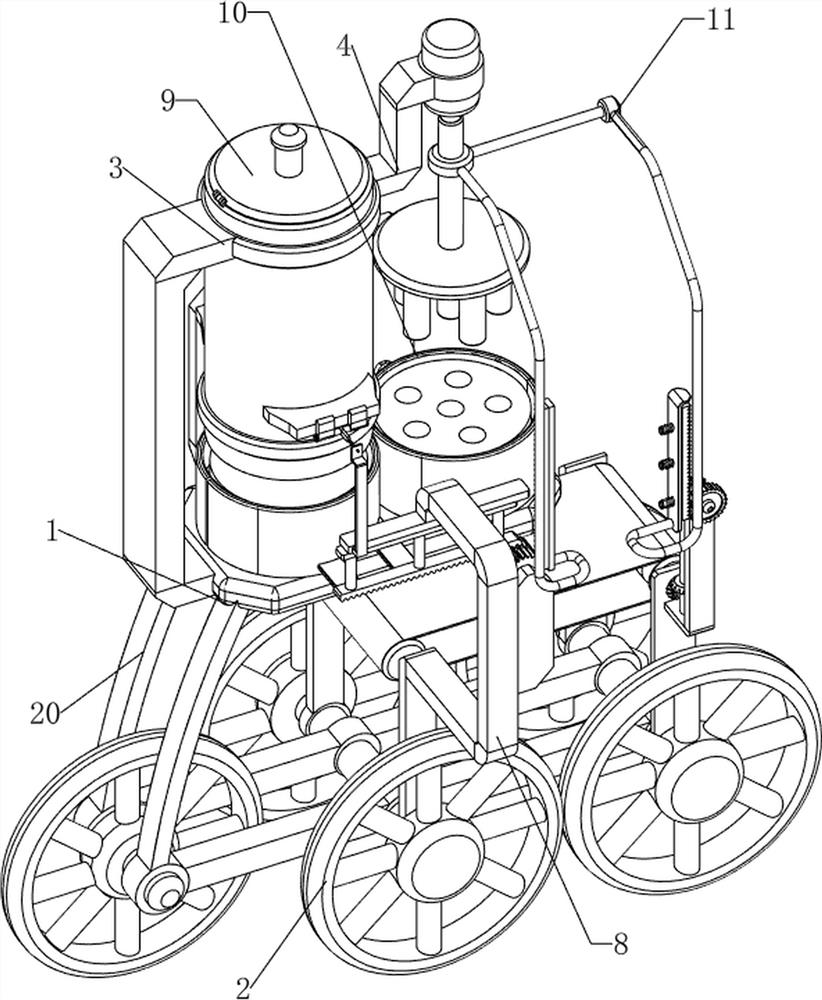
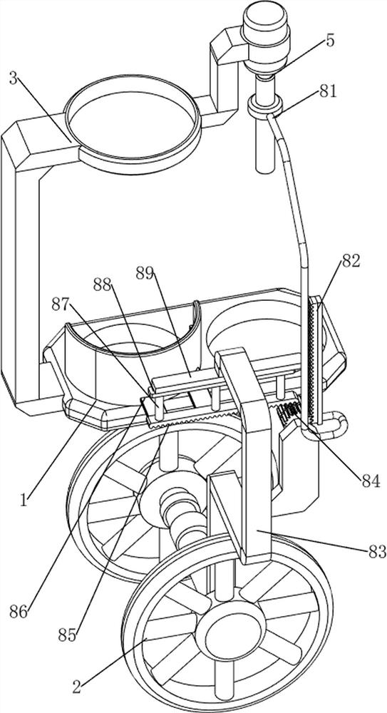
[0026] A new material multi-axis alternate punching machine, such as Figure 1-7 As shown, it includes a first support plate 1, a tire 2, a connecting frame 20, a support frame 3, a first fixed plate 4, a cylinder 5, a second fixed plate 6, a punching rod 7, a transmission mechanism 8, and a blanking mechanism 9 With the clamping mechanism 10, the bottom of the first support plate 1 is connected with a connecting frame 20, and the front and rear sides of the connecting frame 20 are rotatably equipped with tires 2, and the left side of the connecting frame 20 is also rotatably installed with a tire 2, and the left side of the connecting frame 20 Connected with a support frame 3, the upper part of the right side of the support frame 3 is connected with a first fixed plate 4, a cylinder 5 is installed on the first fixed plate 4, a second fixed plate 6 is connected on the telescopic rod of the cylinder 5, and the second fixed plate 6 The bottom is evenly spaced with punching rods ...

Embodiment 2

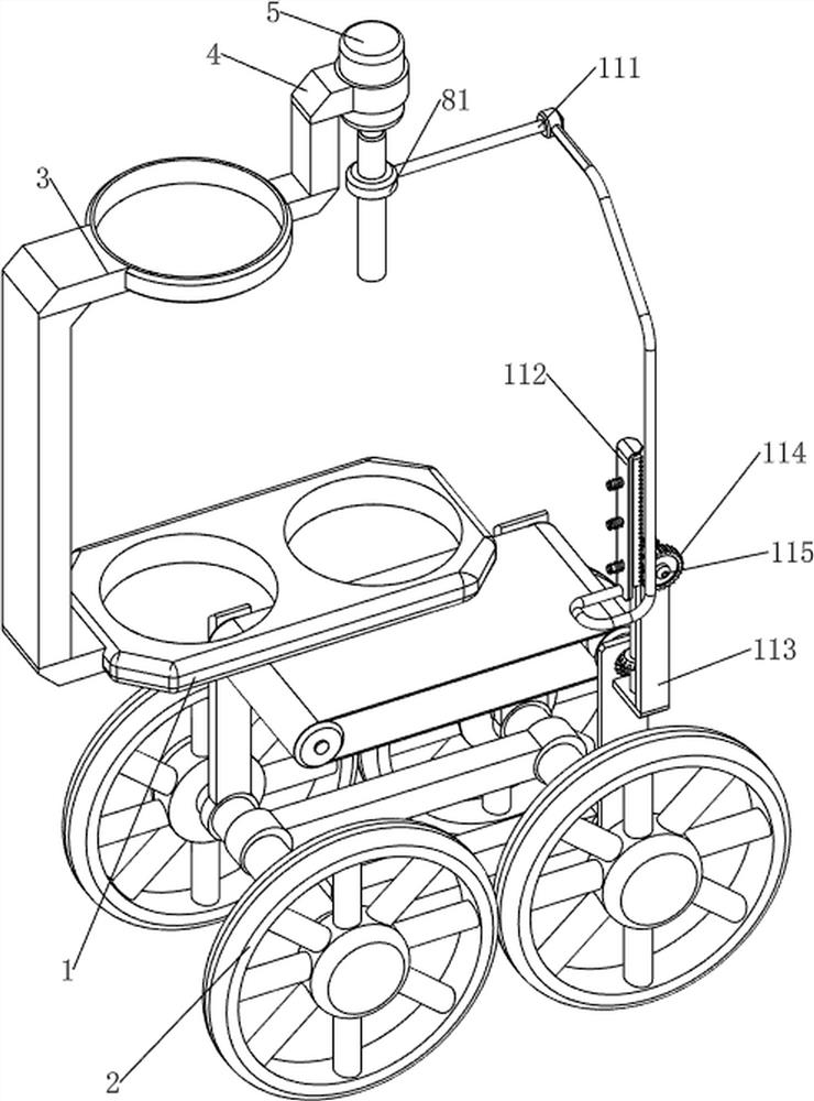
[0032] On the basis of Example 1, such as figure 1 , Figure 8 and Figure 9 As shown, a discharge mechanism 11 is also included, and the discharge mechanism 11 includes a third link 111, a ratchet bar 112, a fifth support plate 113, a ratchet 114, a rotating shaft 115, a second rotating rod 116, the first full bevel gear 117, the third rotating rod 118, roller 119, conveyor belt 1110 and the second full bevel gear 1111, the upper part of the first connecting rod 81 right side is connected with the third connecting rod 111, the third connecting rod 111 bottom is provided with ratchet bar 112, the second A fifth support plate 113 is connected to the right front side of the top of the support plate 1, and the upper part of the fifth support plate 113 is rotatably connected to a rotating shaft 115. A ratchet 114 is installed on the front end of the rotating shaft 115, and the ratchet 114 engages with the ratchet bar 112. The middle part of the fifth support plate 113 The vertic...


PUM


Abstract

The invention relates to a perforating machine, in particular to a new material multi-shaft alternative perforating machine. The technical problem to be solved is to provide the new material multi-shaft alternative perforating machine with high perforating efficiency and high safety. A new material multi-shaft alternative perforating machine comprises a first supporting plate and a connecting frame, and the lower side of the first supporting plate is connected with the connecting frame; the tire is rotationally mounted at the lower part of the connecting frame; and one side of the connecting frame is connected with the supporting frame. A plurality of holes can be drilled at a time through the punching rod, the punching efficiency is improved, new materials can be clamped through the first clamping plate and the second clamping plate, people do not need to manually press the new materials, the safety is improved, the punched new materials can be conveyed out through the discharging mechanism, and people can conveniently collect the new materials.

Description

technical field [0001] The invention relates to a punching machine, in particular to a multi-axis alternate punching machine for new materials. Background technique [0002] With the advancement of science and breakthroughs in technology, the application of new materials is becoming more and more extensive. During the manufacturing process of new materials, it is necessary to punch holes in new materials. Drilling a hole is not efficient, and people need to manually press the new material, which is not safe. [0003] We have developed a device with high drilling efficiency and high safety to solve the current problems. Contents of the invention [0004] In order to overcome the relatively simple structure of most current drilling equipment, only one hole can be drilled at a time, the drilling efficiency is not high, and people need to manually press the new material, which is not safe. The technical problem is: provide a A new material multi-axis alternate punching machi...

Claims


Application Information

Patent Timeline
IPC IPC(8): B26D7/04B26F1/16B26D7/32
CPCB26D7/04B26F1/16B26D7/32
Inventor 徐娜
Owner 徐娜
Why Eureka
Try Eureka