

Ceramic tile joint filling device for building decoration
A ceramic tile and building technology, applied in the direction of architecture and building structure, can solve the problems of low accuracy, time-consuming and laborious, and achieve the effect of high accuracy and enhanced joint filling effect.
- Summary
- Abstract
- Description
- Claims
- Application Information
AI Technical Summary
Problems solved by technology
Method used
Image

Examples
Embodiment 1
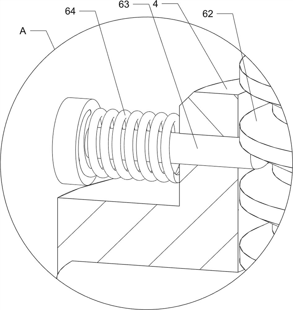
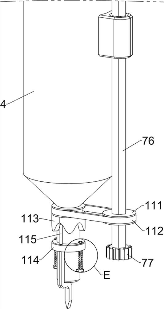
[0037] A kind of ceramic tile caulking device for building decoration, refer to Figure 1-Figure 8 , including a slide rail 1, a first support rod 2, a casing 3, a storage tank 4, a storage frame 5, a pushing assembly 6, a rotating assembly 7 and a moving assembly 8, and the inner middle part of the slide rail 1 is slidingly provided with two The first support rod 2 is provided with a casing 3 between the tops of the first support rod 2, and a storage tank 4 is provided between the inner upper part of the first support rod 2, and the storage tank 4 is located at the inner lower part of the casing 3, on the left side of the casing There is a material storage frame 5, the bottom of the material storage frame 5 communicates with the lower left side of the material storage tank 4, people can put the caulking agent into the material storage frame 5, at this time, some caulking agent will enter the material storage tank 4, a pushing assembly 6 is provided on the inner upper part of ...
Embodiment 2
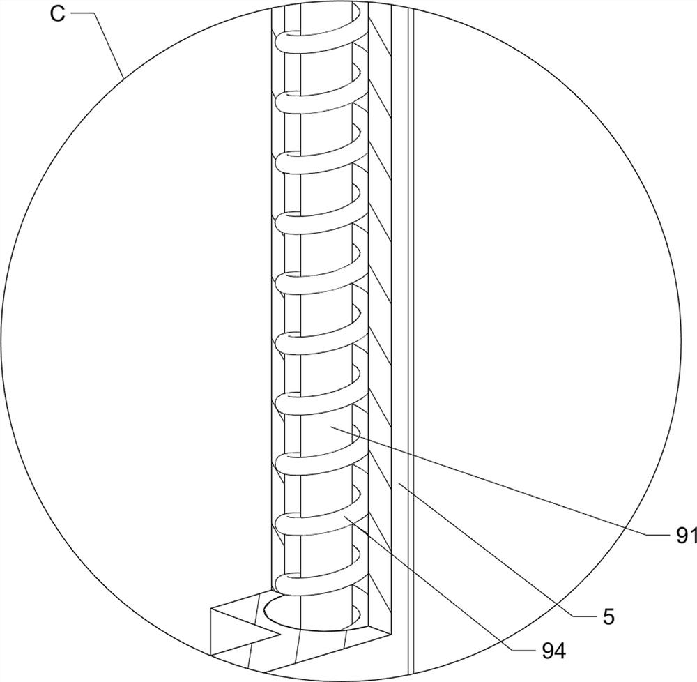
[0043] On the basis of embodiment 1, refer to figure 1 , figure 2 , Figure 9 with Figure 10 , also includes a stirring assembly 9, the stirring assembly 9 includes a dust cover 91, a second motor 92, a stirring rod 93 and a third spring 94, the inner upper part of the material storage frame 5 is slidably provided with a dust cover 91, dustproof Cover 91 covers material storage frame 5 tops, prevents dust from entering in material storage frame 5, and the inboard upper part of dustproof cover 91 is bolted with second motor 92, and the output shaft of second motor 92 is provided with stirring bar 93, and stirring bar 93 is located inside the material storage frame 5, start the second motor 92, you can drive the stirring rod 93 to rotate, thereby the caulking agent in the material storage frame 5 is stirred, the left and right sides of the front and back of the dust cover 91 and the material storage A third spring 94 is provided between the frames 5 .
[0044] When people ...
PUM
 Abstract
Description
Claims
Application Information