Cutter feature point identification method and equipment combining transverse geometric features of adjacent cutter paths

A technology of geometric features and recognition methods, applied in neural learning methods, character and pattern recognition, image enhancement, etc., can solve the problems of difficulty in combining the horizontal geometric feature information of adjacent tool paths, poor applicability and effect, etc., and achieve strong robustness. The effect of stickiness and applicability, strong feature expression ability, high recognition accuracy and recall rate

Pending Publication Date: 2022-03-18
HUAZHONG UNIV OF SCI & TECH +1
View PDF0 Cites 1 Cited by
  • Summary
  • Abstract
  • Description
  • Claims
  • Application Information

AI Technical Summary

Problems solved by technology

[0003] Due to the diversity of the features of the processed parts and the geometric defects expressed by the G code, it is difficult to use the traditional method to solve the problem of

Method used


Image

  • Cutter feature point identification method and equipment combining transverse geometric features of adjacent cutter paths
  • Cutter feature point identification method and equipment combining transverse geometric features of adjacent cutter paths
  • Cutter feature point identification method and equipment combining transverse geometric features of adjacent cutter paths

Examples


Embodiment Construction

[0046] In order to make the object, technical solution and advantages of the present invention clearer, the present invention will be further described in detail below in conjunction with the accompanying drawings and embodiments. It should be understood that the specific embodiments described here are only used to explain the present invention, not to limit the present invention. In addition, the technical features involved in the various embodiments of the present invention described below can be combined with each other as long as they do not constitute a conflict with each other.

[0047] see Figure 4 , with the development of deep learning theory and big data-related technologies, graph neural network emerges as the times require. Graph neural network is a neural network structure used to process graph data, which can directly read non-Euclidean structured data. The identification of feature points provides an idea.

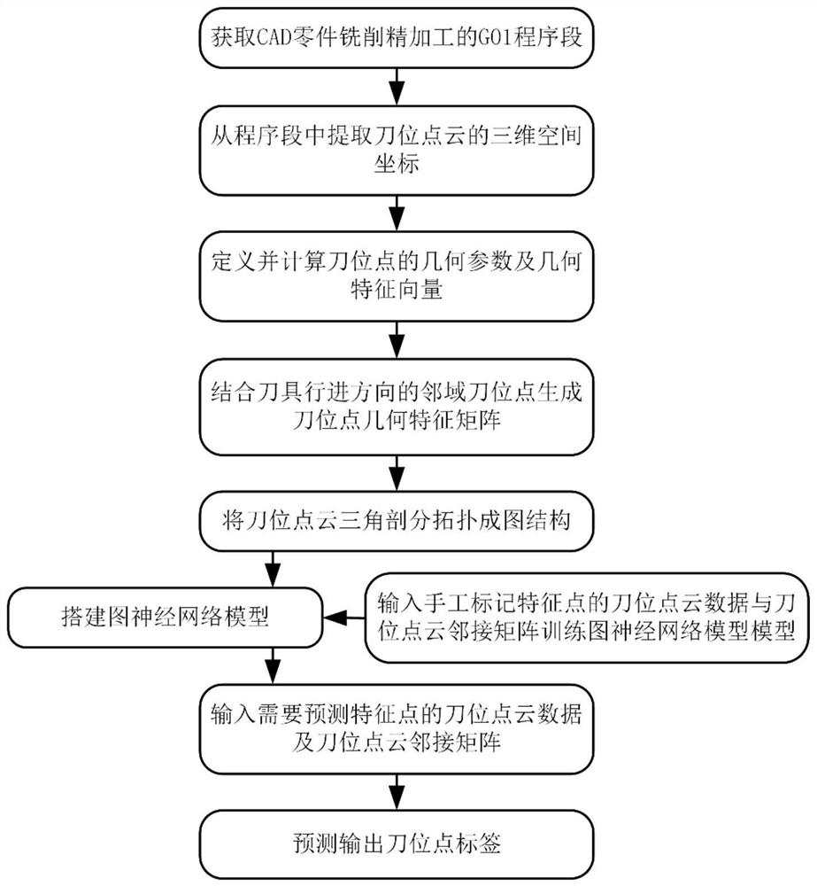
[0048] see figure 1 , Figure 13 , Figure 14 a...


PUM


Abstract

The invention belongs to the related technical field of milling finish machining and deep learning, and discloses a tool feature point recognition method and equipment combining transverse geometric features of adjacent tool paths, and the method comprises the following steps: (1) analyzing a G01 program segment of a target part to obtain three-dimensional coordinates of a tool location point in a machining tool path, sorting according to the advancing direction of the cutter to obtain a cutter location point cloud; (2) determining and calculating geometric parameters of the cutter location points, and constructing geometric feature vectors of the cutter location points; (3) generating a geometric feature matrix of the cutter location points by combining the neighborhood cutter location points in the advancing direction of the cutter; (4) topology is carried out on the cutter location point cloud to form a graph data structure; (5) establishing a communication relation between the cutter location points through the adjacent cutter location point index of each cutter location point, and calculating a cutter location point cloud adjacent matrix; and (6) inputting the cutter location point cloud data of the predicted feature points and the cutter location point cloud adjacency matrix into the trained graph neural network model to complete the recognition of the cutter feature points. The method has higher identification precision and recall ratio.

Description

technical field [0001] The invention belongs to the related technical fields of milling finishing and deep learning, and more specifically relates to a tool feature point recognition method and equipment combined with the lateral geometric features of adjacent tool tracks. Background technique [0002] In modern manufacturing, CNC machining, as one of the most important and popular manufacturing methods, is widely used in automobiles, aviation, consumer electronics and other industries. In the actual milling and finishing process, the G01 block is generated by the post-processing of the CAM software, such as figure 2 As shown, the CNC system reads the G code to process the parts, but the G code is a relatively simple language, which mainly contains the position information of the tool path, and cannot express the geometric characteristics of the part model, so in this process The CNC system cannot obtain the geometric feature information of the part. With the development o...

Claims


Application Information

Patent Timeline
IPC IPC(8): G06V10/46G06V10/764G06V10/82G06K9/62G06N3/04G06N3/08G06T7/00G06T7/73
CPCG06N3/08G06T7/0004G06T7/73G06T2207/20081G06T2207/20084G06T2207/10028G06N3/047G06N3/045G06F18/2415
Inventor 胡鹏程宋颍博谢杰君陈吉红
Owner HUAZHONG UNIV OF SCI & TECH
Why Eureka
Try Eureka