
Smart home access control system

An access control and smart home technology, applied in radio wave measurement systems, cleaning and flexible objects, measuring devices, etc., can solve problems such as power consumption, to avoid leakage of access control unlocking information, good power saving performance, and improve use safety Effect

Pending Publication Date: 2022-03-18
黄碧仁
View PDF0 Cites 0 Cited by
  • Summary
  • Abstract
  • Description
  • Claims
  • Application Information

AI Technical Summary

Problems solved by technology

[0002] With the continuous improvement of people's property safety and anti-theft awareness, the safety performance requirements of the family are also constantly improving, so the smart home access control system has emerged as the times require. The existing smart home access control system is powered by all structures throughout the day. More power-intensive

Method used


Image

  • Smart home access control system
  • Smart home access control system
  • Smart home access control system

Examples


Embodiment 1

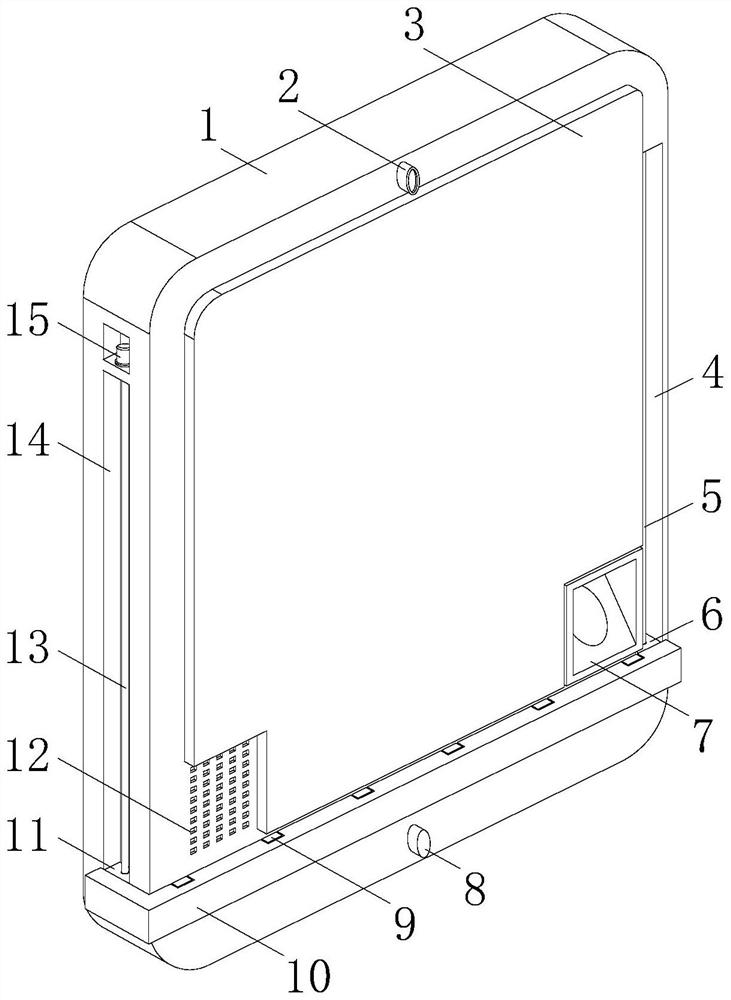
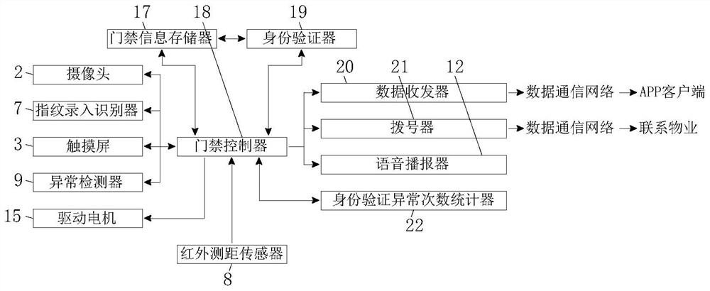
[0021] see Figure 1-3 , the present invention provides the following technical solutions: a smart home access control system, including an access control shell 1, the front of the access control shell 1 is equipped with a touch screen 3, the front of the access control shell 1 is equipped with a camera 2 above the touch screen 3, the access control shell 1 The front side of the touch screen 3 is equipped with a fingerprint entry recognizer 7 and a voice announcer 12 respectively, the inside of the access control shell 1 is equipped with an access control controller 18, and the inside of the access control shell 1 is located on one side of the access control controller 18. Equipped with access control information memory 17, identity verifier 19, data transceiver 20 and identity verification abnormal times counter 22, touch screen 3, camera 2, fingerprint entry recognizer 7, voice broadcaster 12, access control information memory 17, identity verification device 19. The data tr...

Embodiment 2

[0028] The difference of this embodiment compared with embodiment 1 is:

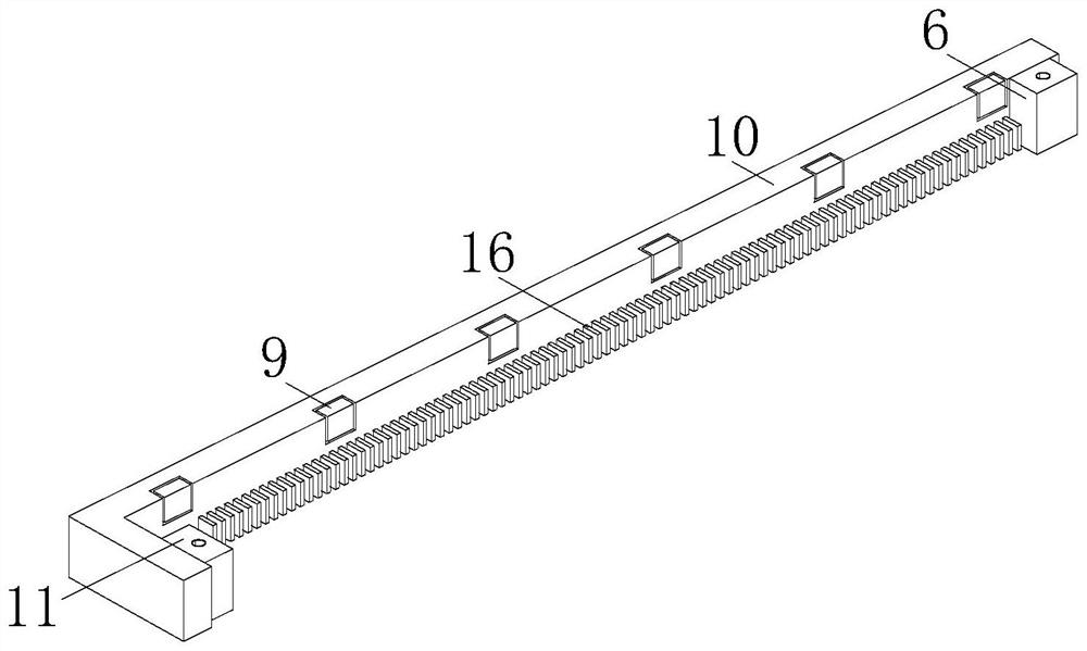
[0029] Specifically, the front of the access control housing 1 is provided with an inspection frame 10, and the access control housing 1 is provided with a driving structure. The driving structure enables the inspection frame 10 to have the function of reciprocating movement, and a plurality of abnormality detectors are equipped at equal intervals above the inner wall of the inspection frame 10. 9. A plurality of abnormality detectors 9 are electrically connected to the access controller 18 , and a cleaning brush 16 is connected to the bottom of the inner wall of the inspection frame 10 .

[0030] Concretely, the drive structure includes two assembly grooves 14 arranged on the side wall of the access control shell 1, the inside of the upper assembly groove 14 is equipped with a drive motor 15, the drive motor 15 is electrically connected with the access control controller 18, and the lower assembly groove...


PUM


Abstract

The invention discloses a smart home access control system, and belongs to the technical field of home safety protection, the smart home access control system comprises an access control shell, a touch screen is assembled on the front side of the access control shell, and a camera is assembled on the front side of the access control shell and located above the touch screen; a fingerprint input identifier and a voice broadcast device are respectively assembled on the front surface of the access control shell and are positioned on two sides of the touch screen; an access controller is assembled in the access control shell; the distance between the human body and the system is measured through the infrared distance measuring sensor, information is transmitted to the access controller only when the human body is in the unlocking range of the system, and the access controller controls the corresponding device to be started, that is, only the infrared distance measuring sensor and the access controller need to be powered to work when the system is not used, so that the system is convenient to use. The safety performance of the system is not affected, and the electric energy saving performance of the system is good.

Description

technical field [0001] The invention belongs to the technical field of home safety protection, and in particular relates to a smart home access control system. Background technique [0002] With the continuous improvement of people's property safety and anti-theft awareness, the safety performance requirements of the family are also constantly improving, so the smart home access control system has emerged as the times require. The existing smart home access control system is powered by all structures throughout the day. It costs more electricity. Contents of the invention [0003] In order to solve the problems raised in the above-mentioned background technology. The invention provides an intelligent home access control system, which has the characteristics of good system safety performance and good power saving performance. [0004] In order to achieve the above object, the present invention provides the following technical solutions: a smart home access control system,...

Claims


Application Information

Patent Timeline
IPC IPC(8): G07C9/37G01S11/12B08B11/04B08B1/00
CPCG07C9/37B08B11/04G01S11/12B08B1/12B08B1/30
Inventor 黄碧仁
Owner 黄碧仁
Learn More