

Energy-saving speed regulation device and method for low-pressure heater drain pump
A technology of speed regulating device and drain pump, applied in electromechanical devices, pump control, mechanical energy control and other directions, can solve the problems of friction and wear, shorten the service life of equipment, increase power consumption and other problems, achieve low heat generation, convenient open-loop or closed-loop The effect of high operation and comprehensive power saving performance
- Summary
- Abstract
- Description
- Claims
- Application Information
AI Technical Summary
Problems solved by technology
Method used
Image

Examples
Embodiment 1
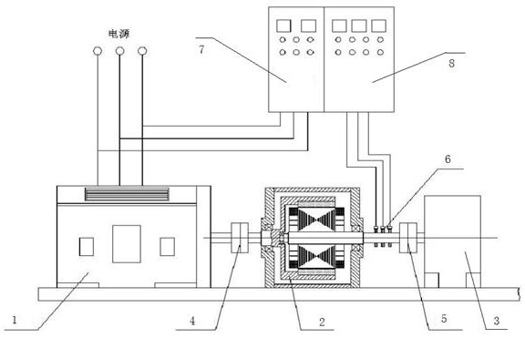
[0045] see figure 1 , 2
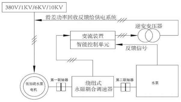
[0046] The winding type permanent magnet speed regulating device is connected between the motor of the low-load drain pump and the water pump. The shaft of the water pump is connected with the motor of the low-load drain pump through a coupling. The coupling includes a first coupling and a second coupling. The motor of the low-load drain pump is connected to the winding permanent magnet speed regulating device through the first coupling, and the winding permanent magnet speed regulating device is connected to the water pump through the second coupling. The second coupling is provided with a collector ring and Carbon brush, when it starts synchronously, the permanent magnet rotor rotates at the same time, forming a speed difference with the winding rotor, driving the second coupling to rotate, the second coupling drives the water pump to pump water, and cuts the magnetic induction line in the winding to generate induction Electromotive force; the con...
Embodiment 2
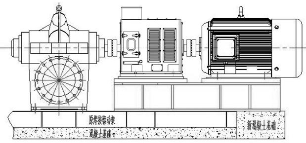
[0049] see image 3
[0050] According to the site conditions, the original overall steel structure support and concrete foundation were remodeled accordingly, and a new drive frame and new foundation were added (that is, the original bracket at the motor support part of the low-load drainage pump was cut off, and this part of the foundation was removed. New On the concrete foundation, the new driving frame made falls on the modified bracket and the new concrete foundation surface, and the low-plus drainage pump motor, winding permanent magnet governor, coupling and water pump are installed on the new driving frame.
[0051](1) Remove the coupling of the motor of the low-load drain pump and the original motor shaft, and hoist the motor of the low-fill drain pump to a safe area;
[0052] (2) Correctly install the winding type permanent magnet speed governor, and connect and fix it through the bolt group to ensure safety and reliability;
[0053] (3) Hoist the motor of the low...
Embodiment 3
[0056] see Figure 4 , 5
[0057] According to the actual output valve throttling adjustment mode of a factory, the motor input power diagram
[0058] Under the minimum load condition, when the flow rate of the water pump is reduced to 72.61t / h by valve throttling, the input power of the motor is 178.54KW, and when the flow rate of the water pump is adjusted to 243.6t / h at the maximum load, the input power of the motor is 205.2 KW.
[0059] Based on these two working points, it is estimated that the average adjustment volume of the pump is about 80% of the rated flow rate, and the energy saving comparison before and after the transformation of the winding permanent magnet governor is estimated.
[0060] It can be seen that the flow rate Q is proportional to the speed n of the load, and the head H is proportional to the square of the speed n, and the required shaft power P is proportional to the cube of the speed n. Therefore, when the system needs 80% of the rated flow, by...
PUM
 Abstract
Description
Claims
Application Information