Carbon furnace

A carbon furnace and furnace body technology, applied in the field of carbon sintering equipment, can solve the problems of uneven temperature, large specific resistance, low output, etc., and achieve the effect of improving calcination quality

Inactive Publication Date: 2004-03-17
孙从群
View PDF0 Cites 0 Cited by
  • Summary
  • Abstract
  • Description
  • Claims
  • Application Information

AI Technical Summary

Problems solved by technology

[0003] The disadvantages of this kind of carbon furnace are: 1) The calcination temperature is not uniform, not only the lower layer is high and the upper layer is low, but also the temperature in each calcination channel is not uniform, resulting in poor product quality, the specific resistance is as high as over 1400, and the output is relatively low. ; 2) high energy consumption, must rely on the stove for heating, can not make full use of flammable volatile matter
For this reason, people have done a lot of experiments, such as improving the air supply and adding volatile matter recovery channels, but they have not found a systematic and effective solution.

Method used


Image

  • Carbon furnace
  • Carbon furnace
  • Carbon furnace

Examples


Embodiment Construction

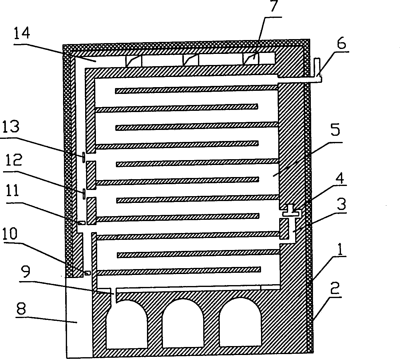
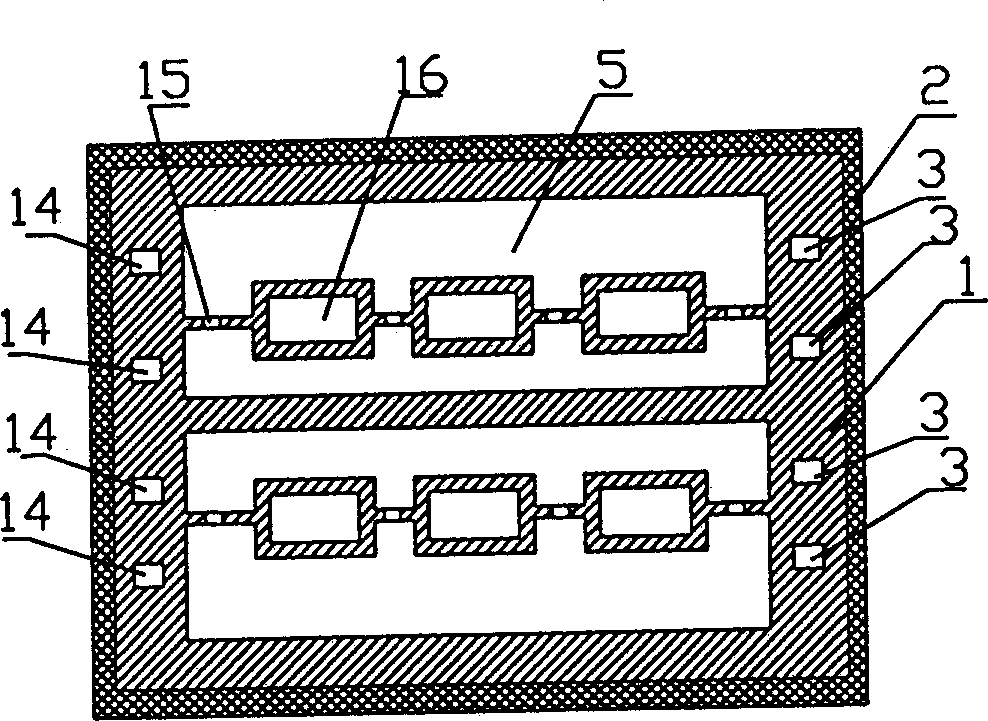
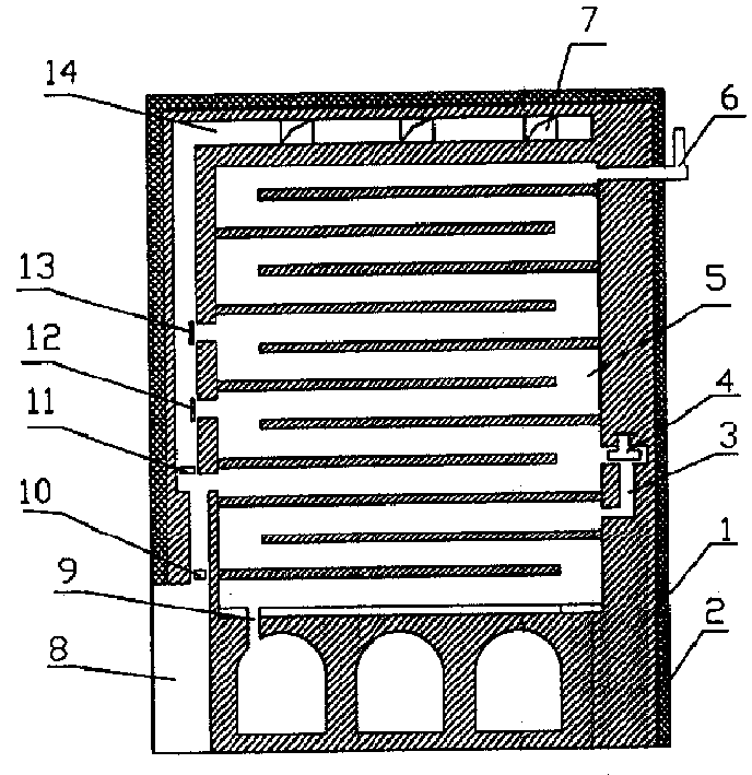
[0014] The carbon furnace described in this embodiment comprises a cuboid body of furnace 1, which is provided with an insulating layer 2 outside, and two furnaces 8 are arranged under the side of the body of furnace 1, and each furnace 8 passes through the gate 10 to two The combustion channel 5 formed by the fire wall of the nine-layer curved back and forth structure supplies heat, and its top is a smoke exhaust port; in this embodiment, there are four combustion channels arranged side by side, and there are three parallel calcined coal channels standing side by side between each two. 16. The coal block used for calcining carbon is put into the upper end of the coal calcination channel—that is, the coal inlet for calcination (no open flame), and finally the finished product is discharged from the lower end—that is, the carbon outlet, and then transported away by the conveying mechanism. In this embodiment, there are two groups of six calcined coal passages 16 . The top of th...


PUM


Abstract

The carbon furnace has several alternately arranged combustion channels and calcination channels inside the furnace body; burner below the body with mouth communicated with the first layer of combustion channels via shutter; volatile component recovering channel inside the body connected to all the combustion channels; and air preheating channel communicated via air regulating board to the first layer of combustion channels. Normally, the carbon furnace may be closed to utilize the recovered volatile component as fuel for maintaining production. It has the advantags of homogeneous calcination temperature, saving in fuel, high yield and quality of product.

Description

Technical field [0001] The invention relates to a carbon firing equipment, in particular to an improved carbon furnace. Background technique [0002] Carbon is widely used in industry. Carbon is formed by calcination of coal at 1200-1300℃ without open flame to remove combustible volatile matter. The calcination or refining of carbon is done by a special carbon furnace. Carbon furnaces in the prior art are generally divided into two types, that is, the direction of the flame used for calcination is consistent with the movement direction of the coal during the calcination process, which is called a down-flow calcination furnace; otherwise, it is a counter-flow calcination furnace, namely The coal moves from top to bottom from the combustion channel commonly known as the calciner, and the flame burns from the bottom to the top of the calcination channel around the combustion channel. There is no essential difference between the two. At present, the countercurrent five-layer o...

Claims


Application Information

Patent Timeline
Patent Type & Authority Patents(China)
IPC IPC(8): C01B31/02
CPCY02P20/129
Inventor 孙从群
Owner 孙从群
Why Eureka
Try Eureka