Calcination container and method

A calcination and container technology, applied in the field of calcination, can solve the problems of sample mixing, difficulty in controlling the amount, and inability to accurately control the airflow size.

Inactive Publication Date: 2019-01-25
UNIV OF JINAN
View PDF4 Cites 0 Cited by
  • Summary
  • Abstract
  • Description
  • Claims
  • Application Information

AI Technical Summary

Problems solved by technology

[0003] 1. Easy to mix: When two different samples are calcined together, since there is only one channel, it is easy to mix the samples due to the airflow during operation and experiment, and they cannot be reacted separately and then mixed for reaction
[0004] 2. It is difficult to react separately: the two samples may have different reaction atmospheres during the reaction, but only one gas can be introduced into the single channel, and the reaction can only be carried out under the same atmosph

Method used


Image

  • Calcination container and method
  • Calcination container and method
  • Calcination container and method

Examples


Embodiment 1

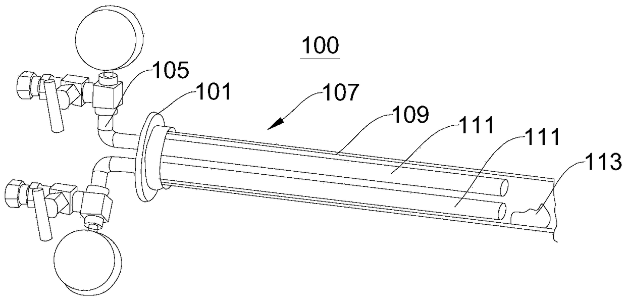
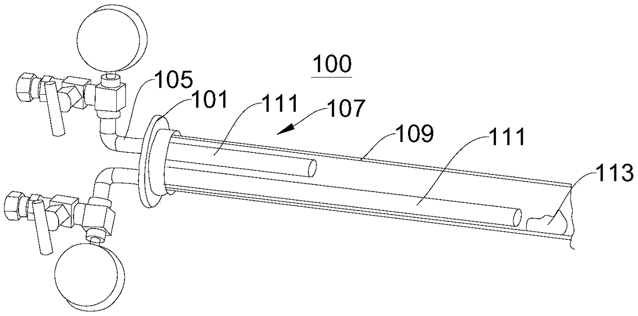
[0050] figure 1 A schematic structural diagram of the first calcining vessel 100 provided in this embodiment. see figure 1 , the present embodiment provides a calcining container 100 , including: a flange 101 , at least two air inlet passages 105 and a container body 107 . The flange 101 is used to connect the gas inlet passage 105 and the container body 107, and the container body 107 is used to carry out the calcination reaction in a heated environment.

[0051] In detail, the flange 101 is provided with at least two gas inlets; the gas inlet channel 105 is connected to the gas inlets one by one, and is used to feed the reaction gas into the gas inlet; the container body 107 is used to heat the reaction gas, Thereby, the calcination operation is carried out, and the container body 107 includes a large quartz tube 109 and at least two small quartz tubes 111, the two small quartz tubes 111 are arranged in the large quartz tube 109, and the small quartz tubes 111 are arranged...

Embodiment 2

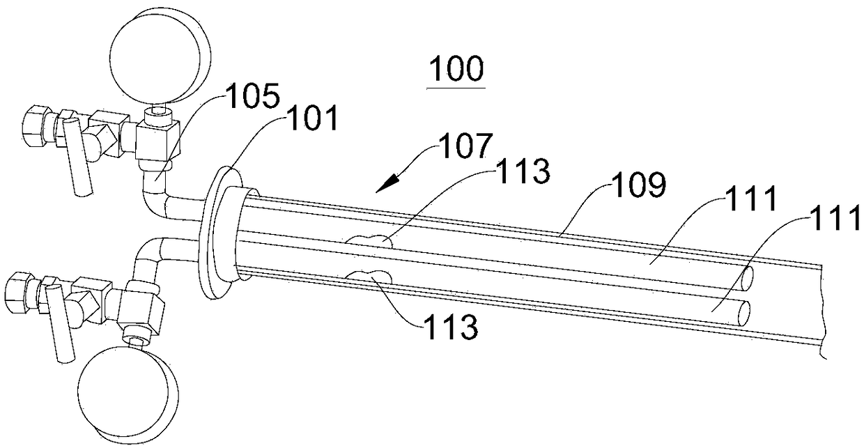
[0066] image 3 A schematic structural diagram of the calcining vessel 100 provided in this embodiment. see image 3 The difference between the calcining container 100 provided in this embodiment and the calcining container 100 provided in Example 1 is that the gas fed into the gas inlet passage 105 of the calcining container 100 provided in this embodiment is a reactive gas, and the materials 113 to be calcined are respectively placed in two small quartz tubes 111, and the reaction gas is input into the small quartz tubes 111 through the air inlet channel 105, so that the material 113 to be calcined is volatilized in the small quartz tubes 111 and enters the large quartz tube 109 with the reaction gas to carry out Calcination work. Calcination is carried out in this way, multiple samples can be placed in different small quartz tubes 111, so that multiple samples are volatilized under heating, and the calcining operation is carried out as the reaction gas enters the large qu...


PUM


Abstract

The invention discloses a calcination container and method, and relates to the technical field of calcination. The calcination container comprises a flange, at least two air inlet passages and a vessel body, wherein the flange is provided with at least two air inlets; the air inlet passages and the air inlets are connected in one-to-one correspondence for introducing gas; the container body is used for performing calcination and comprises a large quartz tube and at least two small quartz tubes, wherein the small quartz tubes are located in the large quartz tube, and the small quartz tubes arein one-to-one correspondence with the air inlets. The calcination container has the advantages that two samples can be separately placed in the small quartz glass tubes, so that the samples cannot bemixed with each other during experiments and operation; different atmospheres are introduced through the two air inlets of the flange respectively to meet different reaction conditions required for the experiments; the flow rate of the gas in different air inlets can be controlled respectively, and the ratio of the amount of two substances can be adjusted by adjusting the flow rate; the placementpositions of the samples and the temperature zone position of the reaction between the two samples can be controlled by designing the length of different small quartz tubes.

Description

technical field [0001] The invention relates to the technical field of calcination, in particular to a calcination container and a calcination method. Background technique [0002] The quartz glass tubes and flanges used for ordinary calcining in the prior art usually have a single gas inlet. The single glass tube channel can meet most of the calcination reactions, but there are still some disadvantages in the process of use, such as two-phase co-volatility reactions: [0003] 1. Easy to mix: When two different samples are calcined together, since there is only one channel, it is easy to mix the samples due to the air flow during operation and experiment, and they cannot be reacted separately and then mixed. [0004] 2. It is difficult to react separately: the two samples may have different reaction atmospheres during the reaction, but only one gas can be fed into the single channel, and the reaction can only be carried out under the same atmosphere. [0005] 3. It is diff...

Claims


Application Information

Patent Timeline
IPC IPC(8): F27B17/02B01J12/00
CPCF27B17/02B01J12/00
Inventor 周伟家刘慧贾进赵莉莉刘震刘宏
Owner UNIV OF JINAN
Why Eureka
Try Eureka