Special waste anti-pollution recovery device for laboratory
A recovery device and anti-pollution technology, applied in separation methods, filtration separation, chemical instruments and methods, etc., can solve problems such as environmental pollution, waste liquid overflow, inconvenient disposal, etc., achieve good crushing effect, facilitate recycling, and prevent sludge blocking effect
- Summary
- Abstract
- Description
- Claims
- Application Information
AI Technical Summary
Problems solved by technology
Method used
Image

Examples
Embodiment Construction
[0025] The following will clearly and completely describe the technical solutions in the embodiments of the present invention with reference to the accompanying drawings in the embodiments of the present invention. Obviously, the described embodiments are only some of the embodiments of the present invention, not all of them. Based on the embodiments of the present invention, all other embodiments obtained by persons of ordinary skill in the art without making creative efforts belong to the protection scope of the present invention.
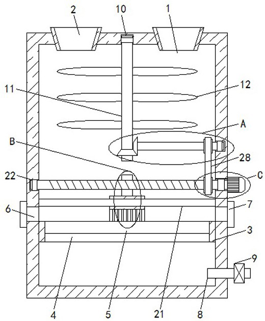
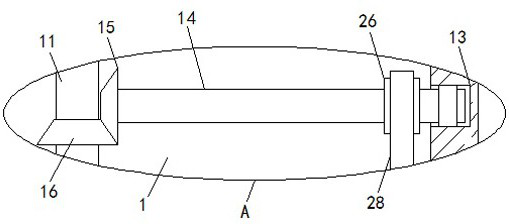
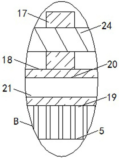
[0026] see Figure 1-4 , a laboratory-specific waste anti-pollution recovery device, comprising a waste treatment box 1, a feed hopper 2 is fixedly connected to both sides of the top of the waste treatment box 1, and a partition plate 3 is fixedly connected to the side wall of the waste treatment box 1 , the separation plate 3 is provided with a screening port 4, the screening port 4 is fixedly connected with a screening plate 5, both sides of th...
PUM
 Abstract
Description
Claims
Application Information
PatSnap Eureka turns technology decisions into work you can execute. Powered by our Innovation Knowledge Graph, it runs expert workflows across engineering, life sciences, materials and intellectual property. Get your review-ready output in minutes.


