Eureka AIR delivers breakthrough ideas for toughest innovation challenges, trusted by R&D personnel around the world.

Improved cutter structure of air conditioner fin mold

An air-conditioning fin and improved technology, applied in the field of improved cutter structure, can solve the problems of easy sticking, no anti-sticking layer installed, waste, etc., and achieve the effect of preventing sticking and good use effect.

Pending Publication Date: 2022-03-22
WUXI MICRO RES
View PDF15 Cites 0 Cited by
  • Summary
  • Abstract
  • Description
  • Claims
  • Application Information

AI Technical Summary

Problems solved by technology

The slitting knife of the air-conditioning fin mold has a simple structure and is easy to implement. It sets a toothed groove at the middle of the blade of the slitting knife and the slopes at both ends, and utilizes the transverse slit on the toothed groove to cut the slit on the slitting knife. During the longitudinal cutting process, the corresponding horizontal cutting and tearing of the generated burrs separate the burrs from the product, which effectively improves the product quality. However, the structure of the cutter is an integrated structure. If the cutter is damaged, the entire cutter needs to be removed. The knife is scrapped, very wasteful
[0005] 2. The improved cutter structure of the traditional air-conditioning fin mold does not have an anti-sticking layer. When cutting, it is prone to sticking, which will affect the shape of the fins.

Method used


Image

  • Improved cutter structure of air conditioner fin mold
  • Improved cutter structure of air conditioner fin mold
  • Improved cutter structure of air conditioner fin mold

Examples


Embodiment 1

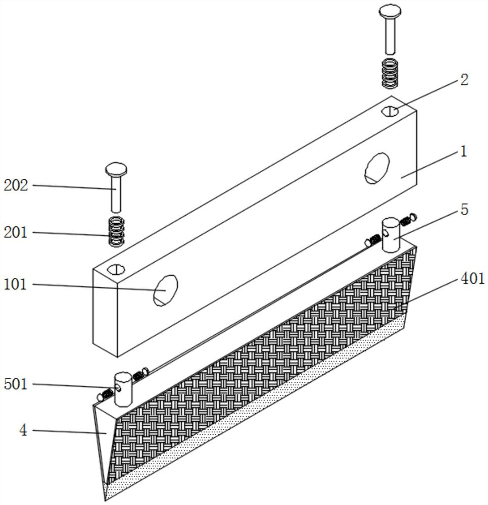
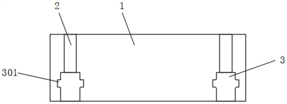
[0027] Embodiment 1, including a mounting plate 1, a mounting groove 2, a connecting groove 3 and a cutting blade 4, the top of the mounting plate 1 is symmetrically provided with a mounting groove 2, and the front of the mounting plate 1 is symmetrically opened with a fixing hole 101, and the mounting plate 1 starts To the effect of installation, the cutter can be installed through the installation plate 1, and also provide space for the opening of the fixing hole 101. The fixing hole 101 plays a role of fixing, providing space for the fixing of the installation plate 1, and the installation groove 2 The first spring 201 is installed inside, and the top of the first spring 201 is equipped with a pressing rod 202, and the bottom end of the pressing rod 202 runs through the bottom of the installation groove 2, and the installation groove 2 provides an installation position for the installation of the first spring 201, so that it It can be installed. The top of the first spring 2...

Embodiment 2

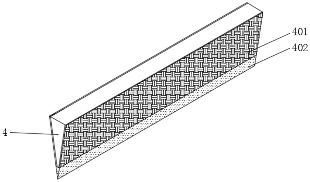
[0029] The second embodiment includes a mounting column 5 , which is symmetrically installed on the top of the cutting blade 4 , and the mounting column 5 corresponds to the connecting groove 3 .

[0030] see Figure 4 , an embodiment provided by the present invention: an improved cutter structure of an air-conditioning fin mold;

Embodiment 3

[0031] Embodiment 3 includes installation holes 501, and the two sides of the installation column 5 are symmetrically provided with installation installation holes 501, and the two sides of the installation column 5 are installed with the second spring 502 through the installation holes 501, and one end of the second spring 502 is installed with a fixing button 503, and the fixed button 503 fits with the fixed groove 301, and the mounting column 5 corresponds to the connecting groove 3, providing a position for the opening of the mounting hole 501, and the mounting hole 501 is used to install the second spring 502, so that the second spring 502 can After installation, the second spring 502 makes the fixed button 503 movable after being squeezed, and then the fixed button 503 is fixed in the fixed groove 301 by the elastic potential energy generated by the extrusion, and the fixed button 503 enters the fixed groove 301, so that A cutting blade 4 can be installed.

[0032] Worki...


PUM


Abstract

The improved cutter structure of the air conditioner fin mold comprises a mounting plate, connecting grooves and cutter blades, mounting grooves are symmetrically formed in the top of the mounting plate, the connecting grooves are symmetrically formed in the bottom of the mounting plate, and the tops of the connecting grooves are connected with the bottoms of the mounting grooves; and a cutting blade is mounted at the bottom of the mounting plate, an anti-sticking layer is mounted on the outer side of the cutting blade, mounting columns are symmetrically mounted at the top of the cutting blade and correspond to the connecting grooves, and mounting holes are symmetrically formed in the two sides of each mounting column. A pressing rod is pressed downwards, so that the pressing rod makes contact with the top of a mounting column, pressure is applied downwards to the mounting column, and a fixing button leaves a fixing groove under the action of a second spring, so that a cutting blade is detached, if the cutting blade is damaged, only one cutting blade needs to be replaced, and the whole cutting blade does not need to be replaced; and waste is avoided.

Description

technical field [0001] The invention relates to the technical field of air-conditioning fin molds, in particular to an improved cutter structure of an air-conditioning fin mold. Background technique [0002] The air conditioning fin is a thin metal sheet arranged on the exhaust pipe, which is in contact with the exhaust pipe to increase the heat exchange area of ​​the exhaust pipe and dissipate the heat of the exhaust pipe into the air. The heat dissipation fin is generally made of aluminum sheet or copper sheet. [0003] The defects in the improved cutter structure of the existing air-conditioning fin mold are: [0004] 1. Patent document CN103191972B discloses a slitting knife for an air-conditioning fin mold, "The invention discloses a slitting knife for an air-conditioning fin mold, including a slitting knife, and the blade of the slitting knife has a tooth shape groove, and both ends of the blade are provided with inclined surfaces, the width of the toothed groove is ...

Claims


Application Information

Patent Timeline
Patent Type & Authority Applications(China)
IPC IPC(8): B21D28/14B21D37/04B21D53/02
CPCB21D28/14B21D37/04B21D53/022
Inventor 陈兆茂叶钦海朱海燕陈红梅
Owner WUXI MICRO RES
Why Eureka
Eureka Blog
Learn More