
Punching and milling all-in-one machine

An all-in-one, punching and milling technology, applied in metal processing equipment, perforation tools, manufacturing tools, etc., can solve the problems of cumbersome processing process, low efficiency, high labor cost, reduce safety hazards, improve flexibility, and improve processing efficiency. Effect

Pending Publication Date: 2022-03-22
深圳市正良制品有限公司
View PDF14 Cites 3 Cited by
  • Summary
  • Abstract
  • Description
  • Claims
  • Application Information

AI Technical Summary

Problems solved by technology

[0002] The structure of atomizing core accessories is as follows: Figure 10 As shown, it is necessary to punch holes and punch grooves around the accessories during processing, and the shapes of the grooves include round, special-shaped holes, single and double grooves with openings, etc. The conventional operation is to realize the holes on the surface by punching machines Processing, and then through the milling machine to process the notch, so the processing of this accessory needs to be completed by two separate equipment, each processing needs to be manually loaded, manually unloaded, and then manually transferred, after the transfer requires Secondary positioning leads to cumbersome processing, low efficiency and high labor costs

Method used


Image

  • Punching and milling all-in-one machine
  • Punching and milling all-in-one machine
  • Punching and milling all-in-one machine

Examples


no. 2 example

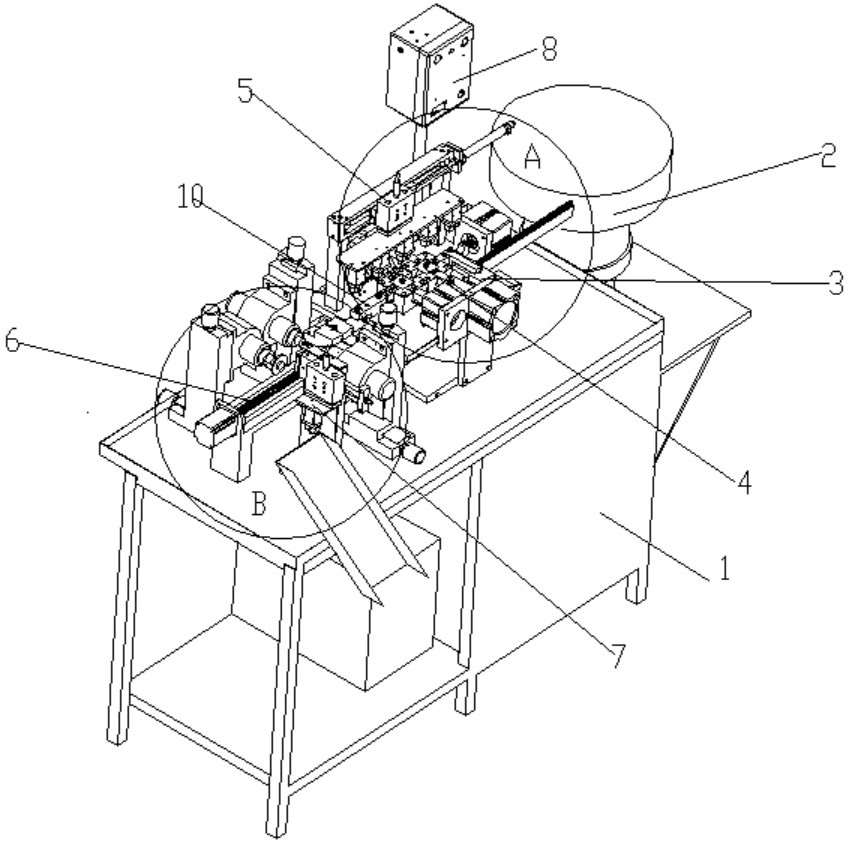
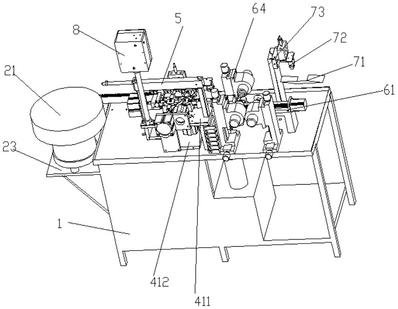
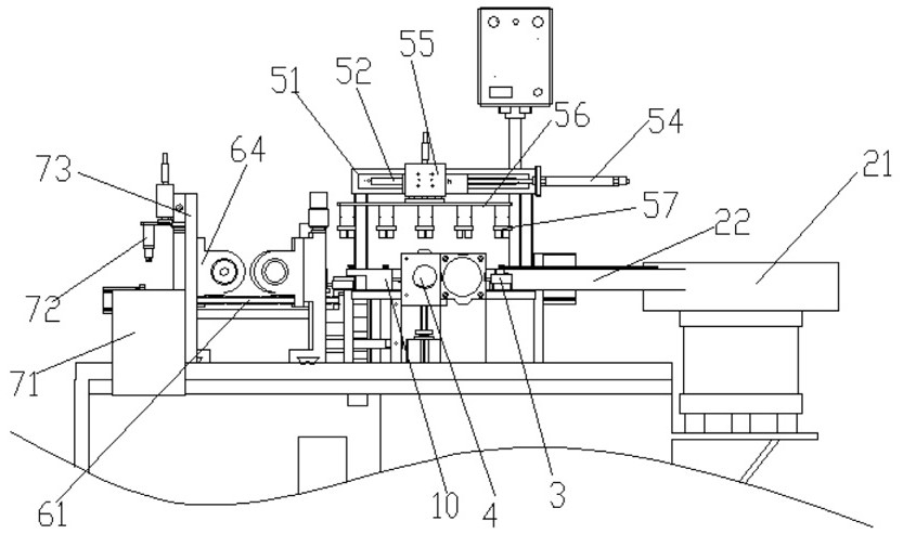
[0050] refer to Figure 8-9 , an integrated punching and milling machine disclosed by the present invention, the specific structure includes a cabinet 1, a vibrating feeding mechanism 2 installed on the cabinet, a moving material receiving mechanism 3, a multi-directional punching mechanism 4, a moving clamping mechanism 5, The multi-station milling mechanism 6, the unloading mechanism 7 and the electric control box 8, the vibrating feeding mechanism vibratingly feeds the parts, and sends the parts to be processed to the mobile material receiving mechanism through the feeding channel, and the mobile material receiving mechanism will The accessories are sent to the clamping and feeding position, the moving clamping mechanism clamps and sends the accessories to be processed to the multi-directional punching mechanism for punching, and then the moving clamping mechanism transfers the punched accessories to the multi-station milling mechanism for multi-station milling. The milling...


PUM


Abstract

The invention discloses a punching and milling machining all-in-one machine which comprises a machine cabinet, a vibration feeding mechanism, a movable material receiving mechanism, a multi-directional punching mechanism, a movable material clamping mechanism, a multi-station milling mechanism, a discharging mechanism and an electric control box, and the vibration feeding mechanism, the movable material receiving mechanism, the multi-directional punching mechanism, the movable material clamping mechanism, the multi-station milling mechanism, the discharging mechanism and the electric control box are installed on the machine cabinet. A to-be-machined accessory is conveyed to the movable material receiving mechanism through the feeding channel, the movable material receiving mechanism conveys the to-be-machined accessory to the clamping and feeding position, the movable material clamping mechanism clamps and conveys the to-be-machined accessory to the multi-directional punching mechanism for punching machining, and then the movable material clamping mechanism conveys the punched accessory to the multi-station milling mechanism. And the machined accessories are subjected to automatic discharging operation through the discharging mechanism. Punching and groove milling synchronous machining of accessories is achieved, the machining efficiency is improved, and the machining cost is reduced.

Description

technical field [0001] The invention relates to the field of machining, in particular to an integrated punching and milling machine. Background technique [0002] The structure of atomizing core accessories is as follows: Figure 10 As shown, it is necessary to punch holes and punch grooves around the accessories during processing, and the shapes of the grooves include round, special-shaped holes, single and double grooves with openings, etc. The conventional operation is to realize the holes on the surface through a punching machine. Processing, and then the processing of the notch by the milling and flattening machine, so the processing of this accessory needs to be completed by two separate equipments. Each processing needs to be manually loaded, manually unloaded, and then manually transferred. After the transfer, it needs Secondary positioning leads to cumbersome processing, low efficiency and high labor costs. Contents of the invention [0003] The purpose of the pr...

Claims


Application Information

Patent Timeline
Patent Type & Authority Applications(China)
IPC IPC(8): B21D43/02B21D28/34B21D28/04B23P23/04
CPCB21D43/027B21D28/34B21D28/04B23P23/04
Inventor 邝振良
Owner 深圳市正良制品有限公司
Learn More