
Mechanical quantitative adjustment torque limiter

A torque limiter and quantitative adjustment technology, which is applied to mechanical equipment, clutches, automatic clutches, etc., can solve problems such as complicated debugging process and inconvenient operation

Active Publication Date: 2022-03-22
QINGDAO BRANCH CO., LTD. OF MECHANICAL SCIENCE RESEARCH INSTITUTE
View PDF5 Cites 0 Cited by
  • Summary
  • Abstract
  • Description
  • Claims
  • Application Information

AI Technical Summary

Problems solved by technology

[0004] The purpose of the present invention is to solve the problems of inconvenient operation and complicated debugging process in the use process of most existing mechanical torque limiters, and propose a mechanical quantitative adjustment torque limiter

Method used


Image

  • Mechanical quantitative adjustment torque limiter
  • Mechanical quantitative adjustment torque limiter
  • Mechanical quantitative adjustment torque limiter

Examples


specific Embodiment approach 1

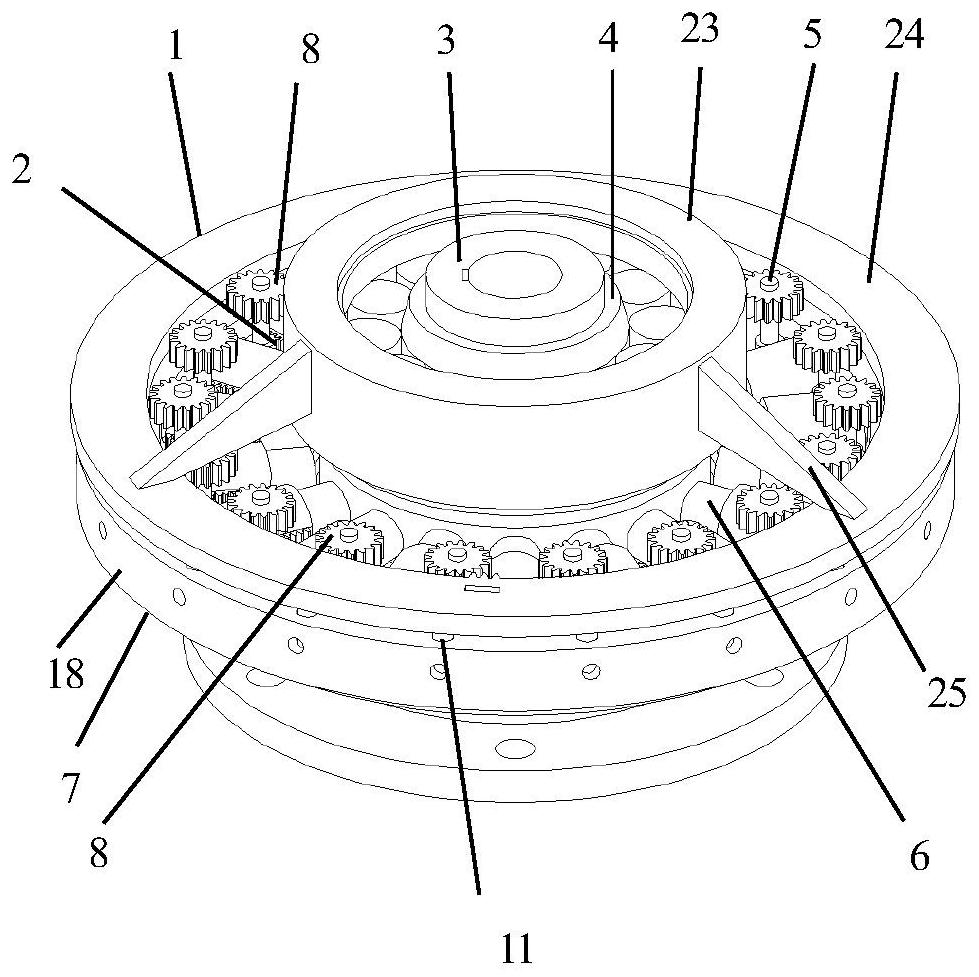
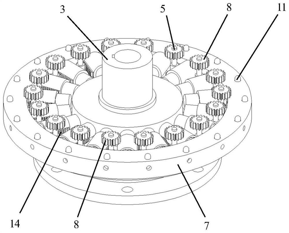
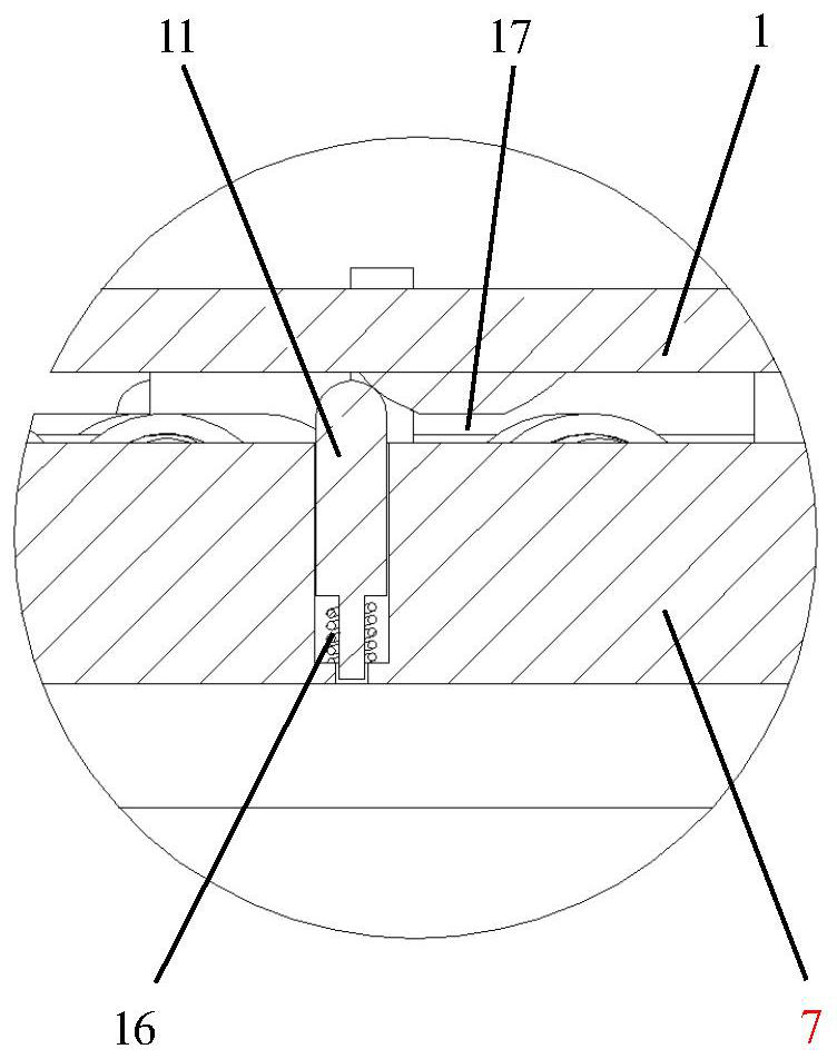
[0035] A mechanical quantitative adjustment torque limiter of this embodiment, such as figure 1 - 8, the composition includes:

[0036] Torque setting dial 1, incomplete gear for limit 2, output shaft 3, rolling bearing at output end 4, rotating shaft 5, a set of friction columns 6, input end flange 7, a set of toggle gear 8, a set of limit Pin 9, a set of limit compression springs 10, a set of guide pins 11, a scale window 12, a set of friction compression column springs 13, a set of limit racks 14, input end rolling bearings 15, a set of guide pin compression springs 16, One set of guide blocks 17;

[0037] A set of friction columns 6, a set of toggle gears 8, a set of limit pins 9, a set of limit compression springs 10, a set of guide pins 11, a set of friction compression column springs 13, a set of limit racks 14, The quantity of one group of guide pin compression springs 16, one group of guide pressing blocks 17 is suitable;

[0038] The following narrative methods an...

specific Embodiment approach 2

[0048] The difference from Embodiment 1 is that a mechanical quantitative adjustment torque limiter of this embodiment, such as figure 1 As shown in - 8, the friction compression column spring 13 is installed in the hole inside the friction column 6, and the friction column 6 has a detent inside to limit the stroke of the friction compression column spring 13.

specific Embodiment approach 3

[0049] Different from the specific embodiment one or two, the mechanical quantitative adjustment torque limiter of this embodiment, such as figure 1 - As shown in 8, the torque setting dial 1 includes an upper outer cover body 23, a lower ring body 24 and a set of waist pieces 25, and the upper outer cover body 23 and the lower ring body 24 are connected through the waist piece 25;

[0050] The torque setting dial 1 is set on the outside of the rolling bearing 4 at the output end through the outer cover body 23;

[0051] The gear tooth structure 22 is arranged on the inner wall of the ring body 24 of the torque setting dial 1;

[0052] A gear tooth structure 22 is provided for meshing with the toggle gear 8;

[0053] The set of guide blocks 17 is arranged on the lower surface of the ring body 24 .


PUM


Abstract

The invention discloses a mechanical quantitative adjustment torque limiter, and belongs to the field of torque limiter mechanical equipment. At present, most mechanical torque limiters do not have the function of quantitatively adjusting and limiting torque according to scales, the torque setting can only be obtained through tests, and operation is inconvenient. The invention provides a mechanical quantitative adjustment torque limiter which is characterized in that an input end flange (7) is coaxially arranged in a disc body of a torque setting drive plate (1), an output shaft (3) is coaxially mounted at the position of a middle hole of the input end flange (7), an input end rolling bearing (15) is sleeved at the input end of the output shaft (3), and an output end rolling bearing (4) is sleeved at the output end of the output shaft (3); and the input end flange (7) applies or eliminates limiting torque to the output shaft (3) through each guide column (19) and the friction column (6) sleeved on the guide column (19). The limiting torque is set through simple operation, the principle is simple, complex debugging work is not needed, and the working efficiency is effectively improved.

Description

technical field [0001] The invention relates to a mechanical quantitative adjustment torque limiter. Background technique [0002] The main function of the torque limiter is overload protection, also known as torque limiter, safety coupling, or safety clutch, which is a component that connects the main machine and the working machine. , it limits the torque transmitted by the transmission system in the form of slipping, and restores the connection when the overload situation disappears, thus preventing mechanical damage and costly shutdown losses. [0003] At present, most mechanical torque limiters do not have the function of quantitatively adjusting the limited torque according to the scale, and the torque setting can only be obtained through experiments, which is inconvenient to operate. In addition, there is also a torque limiter with a scale, which has many operation steps, complicated debugging process and inconvenient use. Contents of the invention [0004] The pu...

Claims


Application Information

Patent Timeline
Patent Type & Authority Applications(China)
IPC IPC(8): F16D43/21
CPCF16D43/21
Inventor 魏伟李云鹏战丽宋琪
Owner QINGDAO BRANCH CO., LTD. OF MECHANICAL SCIENCE RESEARCH INSTITUTE
Learn More