Optical lens module applied to sweeping robot

A sweeping robot and optical lens technology, applied in the direction of optics, optical components, instruments, etc., can solve the problems of inability to guarantee image edge imaging quality, large image edge distortion, etc., to eliminate field curvature, ensure parameter requirements, and clear image quality Effect

Active Publication Date: 2022-03-22
沂普光电(天津)有限公司
View PDF5 Cites 0 Cited by
  • Summary
  • Abstract
  • Description
  • Claims
  • Application Information

AI Technical Summary

Problems solved by technology

However, the existing designs of optical lens modules on the market generally have relatively large distortion at the edge of the image. For example, reference document 1 (application number 202021247233.9) discloses an additional anamorphic lens for a mobile phone, which utilizes a cylindrical mirror (flat Concave cylindrical lens and flat convex cylindrical lens) achieve 1.55 times magnification of the horizontal field of view, and finally achieve a horizontal and vertical field of view angle of 2.75:1, but due to the surface shape of the cylindrical mirror, it is not possible to realize the XY two directions of the edge of the lens The rate of change of field of view is basically the same, so the imaging quality at the edge of the image cannot be guaranteed

Method used


Image

  • Optical lens module applied to sweeping robot
  • Optical lens module applied to sweeping robot
  • Optical lens module applied to sweeping robot

Examples


Embodiment Construction

[0032] The following will clearly and completely describe the technical solutions in the embodiments of the present invention with reference to the accompanying drawings in the embodiments of the present invention. Obviously, the described embodiments are only some of the embodiments of the present invention, not all of them. Based on the embodiments of the present invention, all other embodiments obtained by persons of ordinary skill in the art without making creative efforts belong to the protection scope of the present invention.

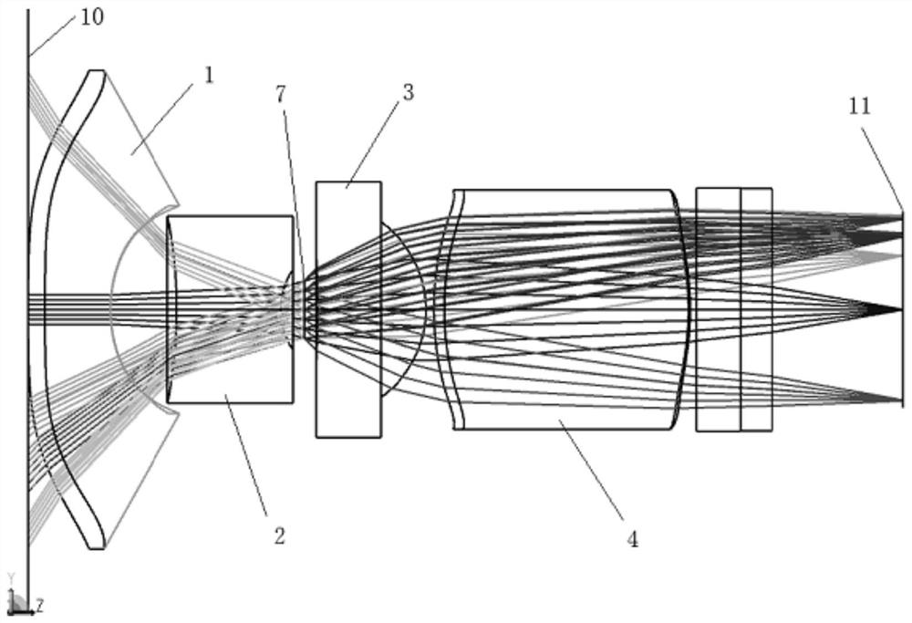
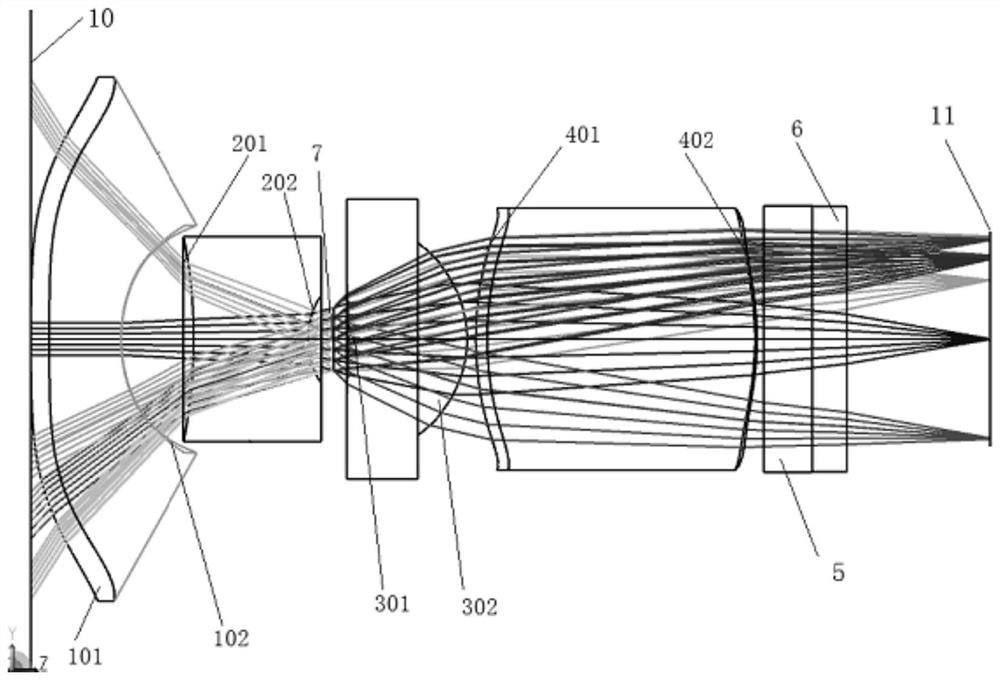
[0033] Such as figure 1 As shown, the present invention provides a first embodiment of an optical lens module applied to a sweeping robot. In this embodiment, the direction of light is incident from the object side 10 along the direction of the image side, and the optical lens module includes A lens one 1, a lens two 2, a lens three 3 and a lens four 4 arranged sequentially from the object side 10 to the image side, and a diaphragm 7 is arranged ...


PUM


Abstract

The invention discloses an optical lens module applied to a sweeping robot, which comprises a first lens, a second lens, a third lens and a fourth lens which are sequentially arranged from an object side to an image side, a diaphragm is arranged between the second lens and the third lens, the first lens comprises a first surface close to the object side and a second surface away from the object side, and the fourth lens comprises a second surface close to the object side and a third surface away from the object side. The surface type structures of the first surface and the second surface meet an equation I, Cy represents the curvature in the Y direction, Cx (y) represents the curvature in the X direction, Ky represents the cone coefficient in the Y direction, X and Y represent the distance between the x direction and the y direction, Z (x, y) represents the coordinate in the z direction, and an, bn, cn... jn, An, Bn... Fn are coefficients; the focal power of the first lens is negative. The two surface types of the first lens have corresponding curvature changes in the X direction and the Y direction, the view field change rates of the edges of the lens in the X direction and the Y direction can be basically the same, image edge distortion is reduced, and meanwhile it can be guaranteed that the transverse large view field angle is achieved.

Description

technical field [0001] The invention relates to the technical field of optical lens modules, in particular to an optical lens module applied to sweeping robots. Background technique [0002] In the application field of sweeping robots, it is required that the optical lens module can achieve different magnification ratios for the horizontal field of view and the vertical field of view, and the horizontal field of view should be as large as possible, while ensuring relatively high imaging quality. However, the existing designs of optical lens modules on the market generally have relatively large distortion at the edge of the image. For example, reference document 1 (application number 202021247233.9) discloses an additional anamorphic lens for a mobile phone, which utilizes a cylindrical mirror (flat Concave cylindrical lens and flat convex cylindrical lens) achieve 1.55 times magnification of the horizontal field of view, and finally achieve a horizontal and vertical field of...

Claims


Application Information

Patent Timeline
Patent Type & Authority Applications(China)
IPC IPC(8): G02B13/18G02B13/06
CPCG02B13/004G02B13/06
Inventor 郭跃武徐航宇李文艳雷禄侯健
Owner 沂普光电(天津)有限公司
Why Eureka
Try Eureka