
Encapsulating equipment capable of passing materials along tangent plane path of rotary powder disc

A section and path technology, applied in the manufacture of encapsulation/enclosure resistors, circuits, encapsulated capacitor devices, etc., can solve the problems of inability to evenly encapsulate, consume large amounts of energy, and cannot be connected, and achieve better encapsulation effects. The effect of avoiding powder and dust

Pending Publication Date: 2022-03-22
汕头市海德电子科技有限公司
View PDF1 Cites 0 Cited by
  • Summary
  • Abstract
  • Description
  • Claims
  • Application Information

AI Technical Summary

Problems solved by technology

At present, there is a defect in this production method, that is, the use of airflow to blow the powder can easily cause a small amount of irregular insulating varnish spots on the pins of the encapsulated electronic components, which can easily lead to failure to connect during installation, and then cannot play the role of electronic components. Some effects, and the use of air blowing consumes a lot of energy, and the dynamic activity of the powder is relatively large, resulting in the inability to be evenly encapsulated, which are all problems

Method used


Image

  • Encapsulating equipment capable of passing materials along tangent plane path of rotary powder disc

Examples


Embodiment Construction

[0016] The present invention will be described in further detail below with reference to the accompanying drawings.

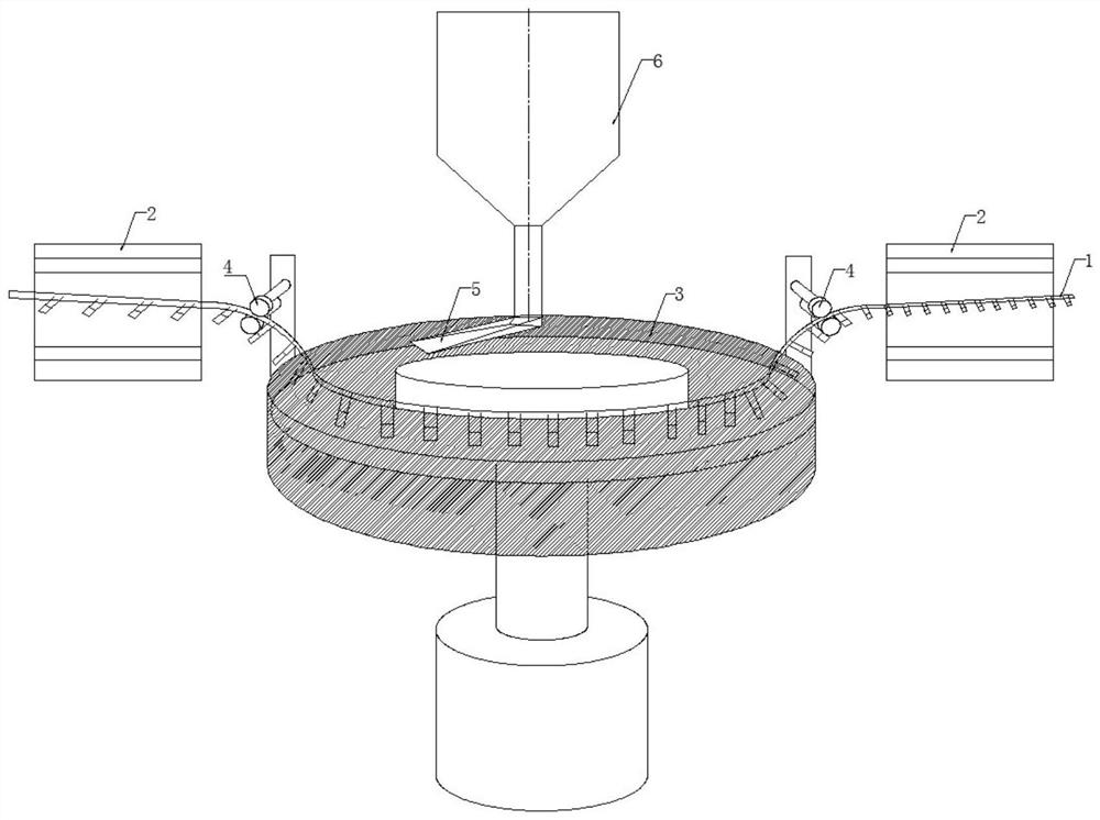
[0017] refer to figure 1 As shown in the figure, an encapsulation device that feeds materials along the cutting surface path of the rotating powder disc has a material belt 1 pulled by a traction mechanism, a heating mechanism 2 and an annular powder groove 3 driven by a motor. Arrange the parts to be encapsulated. The parts to be encapsulated are electronic components with two pins and chips welded at the end, such as thermistors, varistors, ceramic capacitors, etc., and the pins of the electronic components are glued by adhesive tape Attached to the material belt 1, the material belt 1 can be advanced by unwinding and rewinding traction. After being heated by the heating mechanism 2, it enters the ring-shaped powder tank 3 to deposit insulating powder to form an insulating layer.

[0018] Specifically, the two sides above the annular powder trough 3 are prov...


PUM


Abstract

The invention provides packaging equipment capable of passing along a tangent plane path of a rotary powder disc, the packaging equipment is provided with a material belt dragged by a traction mechanism, a heating mechanism and an annular powder groove driven by a motor, a plurality of uniformly distributed to-be-packaged parts are adhered to the material belt, and steering mechanisms are arranged on two sides above the annular powder groove to enable the material belt to steer to enter and exit the annular powder groove. The material belt enters the annular powder groove after passing through the heating mechanism, and the material belt is attached to the inner ring of the annular powder groove to form a wrap angle to advance along with the annular powder groove. Continuous operation is achieved in a belt-shaped material advancing mode, powder is attached to the to-be-encapsulated part through the annular powder groove and the material belt in a relatively static mode, flying dust is avoided, energy is saved, environment friendliness is achieved, the encapsulating effect is better, efficiency is high, and the production cost is saved.

Description

Technical field: [0001] The invention relates to the technical field of electronic component production equipment, in particular to an encapsulation equipment that feeds materials along the cut surface path of a rotating powder disk. Background technique: [0002] Electronic components such as varistors, thermistors and ceramic capacitors need to be heated during production, and then the insulating powder is welded on the outer surface of the electronic components. After repeated heating and welding, the package forms a layer of uniform insulation. Floor. For example, in the Chinese utility model patent CN1792470A, after the double pins are welded with the electronic chip to form the parts to be packaged, the ends of the parts to be packaged in rows are heated and placed in a fluidized bed, and the insulating powder is used to cover the parts to be packaged by air flow. Encapsulated on the package. At present, there is a defect in this production method, that is, the use o...

Claims


Application Information

Patent Timeline
Patent Type & Authority Applications(China)
IPC IPC(8): H01C17/02H01G13/00
CPCH01C17/02H01G13/003
Inventor 田兴海
Owner 汕头市海德电子科技有限公司
Features
  • Generate Ideas
  • Intellectual Property
  • Life Sciences
  • Materials
  • Tech Scout
  • Unparalleled Data Quality
  • Higher Quality Content
  • 60% Fewer Hallucinations
Learn More