
Intelligent installation device for live-line work special-shaped parallel groove clamp

A technology for live work and installation of devices, applied in circuits, electrical components, conductive connections, etc., can solve problems such as large safety hazards, high risk factors, inconvenient operation, etc., to prevent safety accidents, high safety factor, and fast fixing speed. Effect

Pending Publication Date: 2022-03-22
ZHUMADIAN POWER SUPPLY ELECTRIC POWER OFHENAN
View PDF0 Cites 0 Cited by
  • Summary
  • Abstract
  • Description
  • Claims
  • Application Information

AI Technical Summary

Problems solved by technology

[0002] Special-shaped parallel-groove clamp is a contact fitting used for connecting wires in parallel and transmitting electrical loads. It is widely used, such as jumper wires of non-linear pole towers, T-connections at non-load-bearing connections of power systems, branch lines, switches, transformers, etc. The connection of equipment down-conductors, grounding down-conductors of lightning conductors, etc. can be completed by using special-shaped parallel groove clamps. With the continuous improvement of people's quality of life, power grid companies often require that the work on distribution lines should be as fast as possible. Live work is carried out in order to improve the stability and reliability of power supply. The installation of special-shaped parallel groove clamps is mainly manual work, which requires personnel to use insulating rods or insulated tools in the arm car. Special-shaped parallel groove wires The clip parts are small and not fixed, they are easy to fall off during installation, the operation is extremely inconvenient, the installation takes a long time, and it is impossible to judge whether the bolts are fastened in place, and the personnel need to touch the live body many times during the installation process, which poses a great safety hazard and a risk factor high

Method used


Image

  • Intelligent installation device for live-line work special-shaped parallel groove clamp
  • Intelligent installation device for live-line work special-shaped parallel groove clamp
  • Intelligent installation device for live-line work special-shaped parallel groove clamp

Examples


Embodiment 1

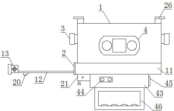
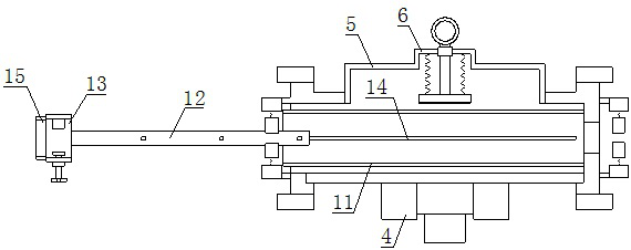
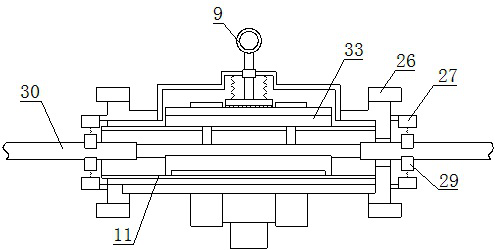
[0030] Such as Figure 1-12 As shown, the intelligent installation device for special-shaped parallel groove clamps for live work includes a clamp body 1, a slave line clamping mechanism 2, a main line clamping mechanism 3 and a bolt fastening mechanism 4, and the rear side of the clamp body 1 is provided with a place Groove 5, the middle part of the placement groove 5 is provided with a clamping frame 6, the inside of the clamping frame 6 is provided with a top shaft 7, and the front and rear ends of the top shaft 7 are respectively provided with a push plate 8 and a pull ring 9 , the rear side of the push plate 8 is provided with a spring A10, and the lower side of the clamp body 1 is provided with a slave wire clamping mechanism 2, and the slave wire clamping mechanism 2 includes a sliding cylinder 11, a suction tube 12 and a clamp Line block 13, the sliding groove 14 is provided on the lower side of the sliding cylinder 11, the suction pipe 12 is arranged inside the slidin...

Embodiment 2

[0038] Such as Figure 1-12 As shown, the intelligent installation device for special-shaped parallel groove clamps for live work includes a clamp body 1, a slave line clamping mechanism 2, a main line clamping mechanism 3 and a bolt fastening mechanism 4, and the rear side of the clamp body 1 is provided with a place Groove 5, the middle part of the placement groove 5 is provided with a clamping frame 6, the inside of the clamping frame 6 is provided with a top shaft 7, and the front and rear ends of the top shaft 7 are respectively provided with a push plate 8 and a pull ring 9 , the rear side of the push plate 8 is provided with a spring A10, and the lower side of the clamp body 1 is provided with a slave wire clamping mechanism 2, and the slave wire clamping mechanism 2 includes a sliding cylinder 11, a suction tube 12 and a clamp Line block 13, the sliding groove 14 is provided on the lower side of the sliding cylinder 11, the suction pipe 12 is arranged inside the slidin...


PUM


Abstract

The invention relates to a live-line work special-shaped parallel groove clamp intelligent installation device which comprises a clamp body, a slave line clamping mechanism, a main line clamping mechanism and a bolt fastening mechanism, a parallel groove clamp is placed in the clamp body, then a main line and a slave line are placed in the parallel groove clamp, and then installation work of the parallel groove clamp is completed. A slave wire is fixed in the drawing pipe, a parallel groove clamp is placed in the clamp body along the placing frame, the parallel groove clamp is clamped by the push plate, when the parallel groove clamp is connected with a main wire, the grip is held tightly to slowly move the clamp body upwards from the lower side of the main wire, the main wire enters the wire clamping plate through the guide frame to be clamped and fixed, the wire clamping block is moved rightwards, and the slave wire is driven by the drawing pipe to enter the sliding barrel. At the moment, the main wire and the auxiliary wire both reach the installation position, a motor is started through a controller, the motor drives a sleeve and a clamping head to rotate, bolts on the outer side of the parallel groove clamp are fastened, and installation is completed; the device has the advantages of being convenient to carry and use, high in stability and high in safety coefficient.

Description

technical field [0001] The invention belongs to the technical field of installation of special-shaped parallel groove clamps, and in particular relates to an intelligent installation device for special-shaped parallel groove clamps for live work. Background technique [0002] Special-shaped parallel-groove clamp is a contact fitting used for connecting wires in parallel and transmitting electrical loads. It is widely used, such as jumper wires of non-linear pole towers, T-connections at non-load-bearing connections of power systems, branch lines, switches, transformers, etc. The connection of equipment down-conductors, grounding down-conductors of lightning conductors, etc. can be completed by using special-shaped parallel groove clamps. With the continuous improvement of people's quality of life, power grid companies often require that the work on distribution lines should be as fast as possible. Live work is carried out in order to improve the stability and reliability of ...

Claims


Application Information

Patent Timeline
IPC IPC(8): H01R11/01H01R11/03H01R4/44
CPCH01R11/01H01R11/03H01R4/44
Inventor 李卫军宋耐超李明明王瑞琦刘洋王洪磊胡海洋张建峰常小伟陈树兵张翼王旭宋占领李楠岳广伟
Owner ZHUMADIAN POWER SUPPLY ELECTRIC POWER OFHENAN
Learn More