
50MW 110kV new energy booster station system

A 50mw110kv, step-up station technology, applied in the direction of emergency power supply arrangement, substation/power distribution device shell, substation/switch layout details, etc., can solve the problems of unfavorable owner unit construction efficiency, improvement, operation and maintenance management inconvenience, etc., to achieve convenience The effect of intensive operation and maintenance management, improving station building efficiency, and improving space utilization

Pending Publication Date: 2022-03-22
HUANENG CLEAN ENERGY RES INST
View PDF0 Cites 0 Cited by
  • Summary
  • Abstract
  • Description
  • Claims
  • Application Information

AI Technical Summary

Problems solved by technology

The differences in the main equipment selection and layout design of each design unit have resulted in different specific forms of the current 50MW 110kV new energy booster station, which cannot achieve standardized design and occupy a large space. It also brings inconvenience to the later unified and intensive operation and maintenance management

Method used


Image

  • 50MW 110kV new energy booster station system
  • 50MW 110kV new energy booster station system
  • 50MW 110kV new energy booster station system

Examples


Embodiment Construction

[0027] In order to enable those skilled in the art to better understand the solutions of the present invention, the following will clearly and completely describe the technical solutions in the embodiments of the present invention in conjunction with the drawings in the embodiments of the present invention. Obviously, the described embodiments are only The embodiments are a part of the present invention, not all embodiments, and are not intended to limit the scope of the present invention. Also, in the following description, descriptions of well-known structures and techniques are omitted to avoid unnecessarily obscuring the concepts disclosed in the present invention. Based on the embodiments of the present invention, all other embodiments obtained by persons of ordinary skill in the art without making creative efforts shall fall within the protection scope of the present invention.

[0028] The schematic diagrams of the structures according to the disclosed embodiments of th...


PUM


Abstract

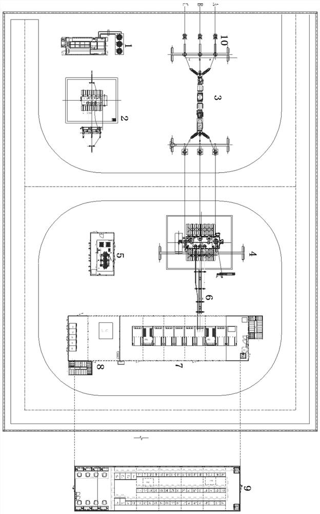
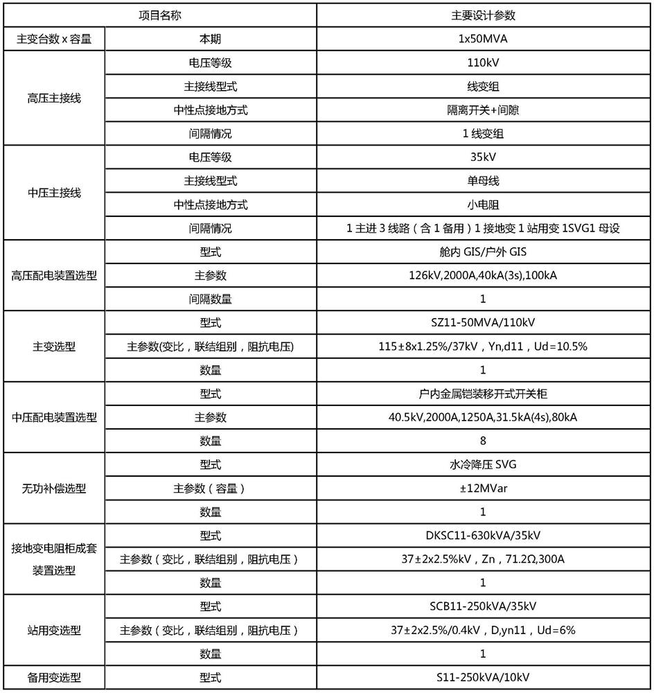
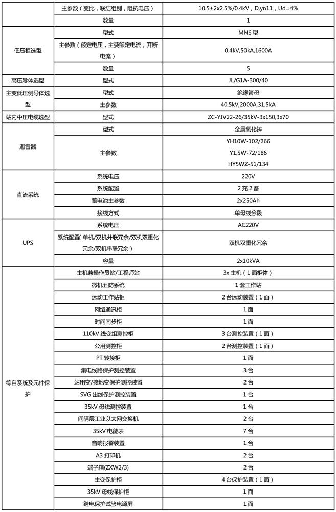
The invention discloses a 50MW 110kV new energy booster station system, which comprises a 110kV power distribution device, a main transformer, an outdoor GIS (Gas Insulated Switchgear), an SVG (Scalable Vector Graphics) step-down transformer / reactor, a high-voltage lightning arrester, a line PT (Potential Transformer) and a prefabricated cabin, the prefabricated cabin comprises an SVG cabin, a grounding transformer cabin, a station transformer and 400V cabin, a 35kV cabin and a secondary equipment cabin; a 35kV power distribution device is arranged in the 35kV cabin; a 400V power distribution device and a station transformer are arranged in the station transformer and 400V cabin; the grounding transformer cabin is internally provided with grounding transformer and resistor complete equipment, the SVG cabin is internally provided with SVG power and control equipment, and the secondary equipment cabin is internally provided with system protection equipment, system communication equipment, system dispatching automation equipment, an integrated automation system and element protection equipment; the 110kV power distribution device is connected with the main transformer, the main transformer is connected with the 35kV power distribution device, the 35kV power distribution device is connected with the reactive power compensation device, the grounding transformer and resistor complete equipment and the station transformer, the standardization of the 50MW 110kV new energy booster station is realized, and meanwhile, the occupied area is small.

Description

technical field [0001] The invention belongs to the field of new energy wind power and photovoltaic power generation, and relates to a 50MW 110kV new energy step-up station system. Background technique [0002] New energy power generation projects such as wind power and photovoltaics are usually composed of two parts: wind power / photovoltaic field area and substation / booster station area. The electric energy generated by the new energy power generation device (wind turbine or photovoltaic module and inverter combination) in the field is boosted by the box transformer, and then connected to the supporting substation / booster station through multiple 35kV collector lines for collection / boosting Send it to the substation of the nearby power grid company in a unified way to realize the grid connection of new energy power. [0003] The 50MW 110kV new energy booster station is a relatively common booster station configuration for wind power, photovoltaic and other new energy power...

Claims


Application Information

Patent Timeline
IPC IPC(8): H02B1/30H02B1/32H02B13/02H02B1/16H02J9/06H02H7/22
CPCH02B1/308H02B1/32H02B13/02H02B1/16H02J9/061H02H7/22
Inventor 吕贝郭辰张立英吴嵩松李玉章高培鑫高建辉张国张庆邓明基邵振州万月林盘盘
Owner HUANENG CLEAN ENERGY RES INST
Learn More