Motor-driven H-bridge circuit
A technology of motor drive and bridge circuit, used in emergency protection circuit devices, DC motor rotation control, excitation or armature current control, etc. Effect
- Summary
- Abstract
- Description
- Claims
- Application Information
AI Technical Summary
Problems solved by technology
Method used
Image

Examples
Embodiment 1
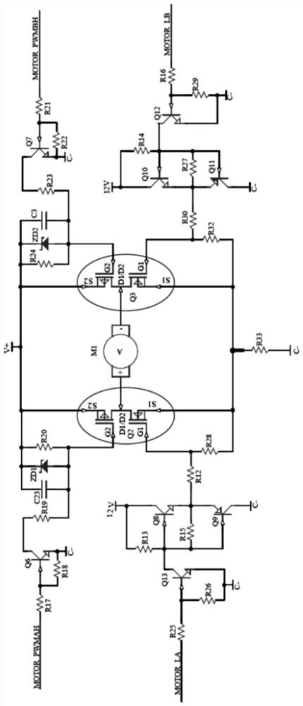
[0020] Such as figure 1 As shown, a motor-driven H-bridge circuit includes: a first forward rotation branch, a first reverse rotation branch, a second forward rotation branch, a second reverse rotation branch, a dual-channel MOS transistor Q2, a dual-channel MOS tube Q3 and the MCU control module, the D1 / D2 poles of the dual-channel MOS tube Q2 are connected to the positive pole of the motor, the D1 / D2 poles of the dual-channel MOS tube Q3 are connected to the negative pole of the motor, and the S2 poles of the dual-channel MOS tube Q2 pole and the S2 pole of the dual-channel MOS transistor Q3 are all connected to the power input terminal V+, the S1 pole of the dual-channel MOS transistor Q2 and the S1 pole of the dual-channel MOS transistor Q3 are connected to a resistor R33 and then grounded;
[0021] The first forward rotation branch is respectively connected to the G2 pole of the dual-channel MOS transistor Q2 and the MCU control module, and the first forward rotation bran...
PUM
 Abstract
Description
Claims
Application Information
 - R&D
- Intellectual Property
- Life Sciences
- Materials
- Tech Scout
- Unparalleled Data Quality
- Higher Quality Content
- 60% Fewer Hallucinations
Browse by: Latest US Patents, China's latest patents, Technical Efficacy Thesaurus, Application Domain, Technology Topic, Popular Technical Reports.
© 2025 PatSnap. All rights reserved.Legal|Privacy policy|Modern Slavery Act Transparency Statement|Sitemap|About US| Contact US: help@patsnap.com