
Electrically-controlled embedded liftable mowing platform

A built-in, header technology, used in headers, cutters, harvesters, etc., can solve the problems of manual adjustment of mowing height, troublesome belt replacement for mowing platform, and reduction of header width. , to avoid overall maintenance and replacement, convenient and quick adjustment, and reduce weight

Pending Publication Date: 2022-03-25
JIANGXI HONGDU AVIATION IND GRP
View PDF5 Cites 0 Cited by
  • Summary
  • Abstract
  • Description
  • Claims
  • Application Information

AI Technical Summary

Problems solved by technology

[0002] At present, most large-scale grassland weeding work power is provided by a tractor, and then connected to a mowing platform (hereinafter collectively referred to as cutting platform). The width of the platform mowing is generally about 2.4 meters. For the rear-mounted header, when it is combined with the tractor, except for the rigid pin connection in the middle connection, other auxiliary connections are connected by soft steel wires. This connection header needs to reach a certain level. Only the weight can ensure the stability of the entire mowing platform when mowing, and manual adjustment is required to adjust the mowing height. In addition, the power shaft from the tractor is directly connected to the gearbox, which makes it very troublesome to replace the belt on the mowing platform; The power transmission of the entire header blades is driven by a gearbox. The number of blades is increased while the cutting width remains unchanged, which reduces the width of the header and reduces the weight a lot. However, the later maintenance is cumbersome. When the gears in the gearbox When damaged, it needs to be disassembled and replaced as a whole

Method used


Image

  • Electrically-controlled embedded liftable mowing platform
  • Electrically-controlled embedded liftable mowing platform
  • Electrically-controlled embedded liftable mowing platform

Examples


Embodiment Construction

[0028] In order to make the technical means, creative features, goals and effects achieved by the present invention easy to understand, the present invention will be further described below in conjunction with specific illustrations.

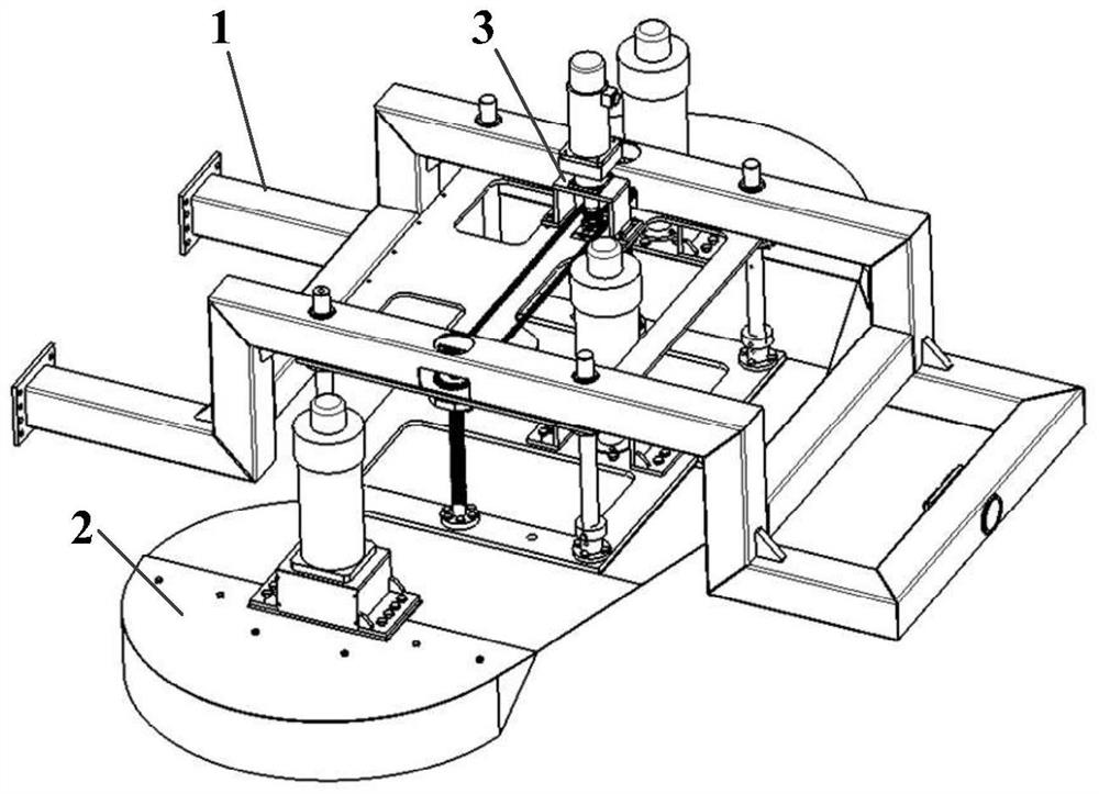
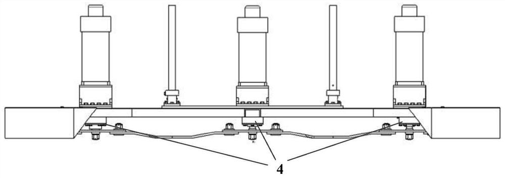
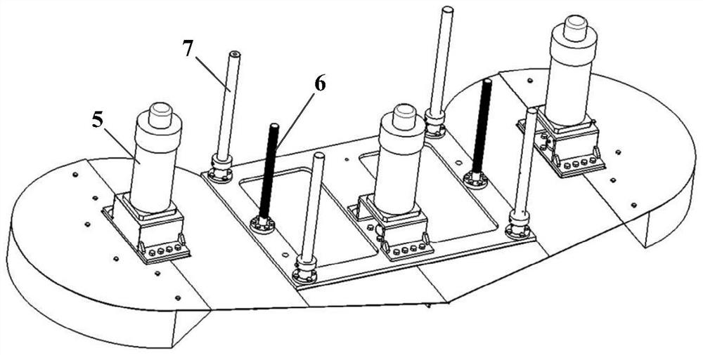
[0029] see Figure 1~5 An electric control built-in liftable mowing platform, including a vehicle frame 1, a header body 2 and a header lifting mechanism 3, wherein, the middle part of the frame 1 is provided with a mower for embedding the header body 2 Groove, described header elevating mechanism 3 is connected with header body 2, and concrete structure is as follows:

[0030] The header body 2 includes a cutter rotation mechanism 4, a mowing motor 5, a lifting screw 6, a lifting guide rod 7 and a header frame, and the header frame is composed of a left frame, a mounting frame and a right frame. And mowing motor 5 is respectively installed on the left bone platform, mounting frame and right bone platform, and mowing motor 5 is V-shaped arrange...


PUM


Abstract

According to the electrically-controlled embedded liftable mowing platform, a groove for embedding a mowing platform body is formed in the middle of a frame, so that the weight of the mowing platform is effectively reduced; a plurality of groups of mowing motors are arranged on the header framework of the header body, the maintainability is good, a cutter rotating mechanism is arranged below each group of mowing motors, two lifting lead screws are symmetrically arranged in the middle of the header framework, one end of each lifting lead screw is fixed on the header framework, and the other end of each lifting lead screw is embedded into the frame. A driving chain wheel nut of the header lifting mechanism is sleeved on one lifting lead screw, a driven chain wheel nut is sleeved on the other lifting lead screw, the upper end of a header lifting motor is installed on the frame, the lower end of the header lifting motor is connected with the driving chain wheel nut sleeved on the lifting lead screw, and the driven chain wheel nut is connected with the driving chain wheel nut. Power output from the header lifting motor serves as a mowing platform transmission mechanism through the two lead screws, so that the mowing platform can stably mow and ascend and descend in the horizontal plane.

Description

technical field [0001] The invention relates to the technical field of mowing platforms, in particular to an electric-controlled built-in liftable mowing platform. Background technique [0002] At present, most large-scale grassland weeding work power is provided by a tractor, and then connected to a mowing platform (hereinafter collectively referred to as cutting platform). The width of the platform mowing is generally about 2.4 meters. For the rear-mounted header, when it is combined with the tractor, except for the rigid pin connection in the middle connection, other auxiliary connections are connected by soft steel wires. This connection header needs to reach a certain level. Only the weight can ensure the stability of the entire mowing platform when mowing, and manual adjustment is required to adjust the mowing height. In addition, the power shaft from the tractor is directly connected to the gearbox, which makes it very troublesome to replace the belt on the mowing pla...

Claims


Application Information

Patent Timeline
Patent Type & Authority Applications(China)
IPC IPC(8): A01D47/00A01D34/63A01D34/82A01D34/74
CPCA01D47/00A01D34/63A01D34/82A01D34/74
Inventor 陈寿辉谢训鹏倪琳轩曹雄伟齐洪豪史小露刘晶孙文心钟媛
Owner JIANGXI HONGDU AVIATION IND GRP
Learn More