

Upper mold core of low-pressure mold and low-pressure mold thereof
A low-pressure mold and mold core technology, which is applied to the mold core of low-pressure molds and the field of low-pressure molds, can solve the problems of not knowing when the cooling is completed, large water consumption, and large floor space. The effect of reducing water consumption and preventing clogging at the outlet
- Summary
- Abstract
- Description
- Claims
- Application Information
AI Technical Summary
Problems solved by technology
Method used
Image

Examples
Embodiment 1
[0032] An upper mold core for a low-pressure mold, comprising:
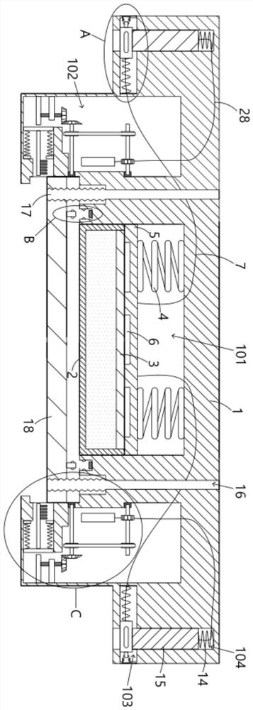
[0033] The main mold 1 is provided with an intermediate cavity 101, a side cavity 102, a horizontal cavity 103, an accommodating cavity 104 and a groove 105. 105 each has two, and symmetrically opened on both sides of the middle cavity 101, the inner wall of the middle cavity 101 is fixedly provided with an open box body 2, the open box body 2 is made of a material with good thermal conductivity, such as aluminum Alloy, pure copper, etc., the top of the open box body 2 is provided with an elastic gasket 3, the elastic gasket 3 has good ductility, such as heat-conducting rubber, etc., the open box body 2 and the elastic gasket 3 are surrounded by The cavities are filled with cooling liquid, which increases in volume when frozen and freezes, and decreases in volume after the ice cube melts. For example, in this embodiment, the cooling liquid can directly choose water, which is commonly used Easy to obtain and low ...
Embodiment 2
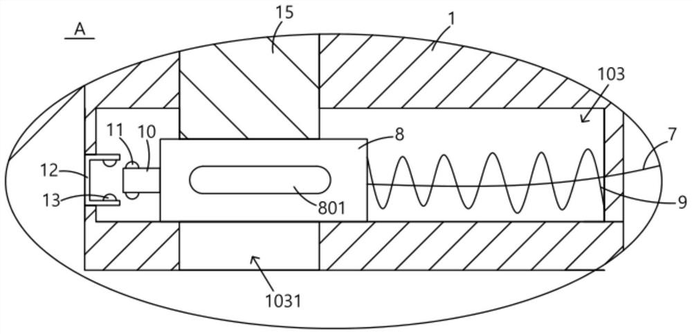
[0041] In this embodiment, on the basis of the first embodiment, the structure of "the end of the blocking block 8 away from the second spring 9 can be snapped and fixed in the transverse cavity 103" is further specifically defined: the blocking block 8 is far away from the second spring 9 An extension rod 10 is fixedly arranged at one end of the extension rod 10, a first raised portion 11 is fixedly arranged on the extension rod 10, a positioning frame 12 is fixedly arranged on the inner side wall of the transverse chamber 103, and a second raised portion 13 is fixedly arranged in the positioning frame 12 , the second protruding portion 13 can limit and fix the first protruding portion 11, and when in use, the blocking block 8 can be pushed toward the direction close to the positioning frame 12 until the first protruding portion 11 on the extension rod 10 When being limited by the second protrusion 13 in the positioning frame 12, the blocking block 8 at this time is relatively...
Embodiment 3
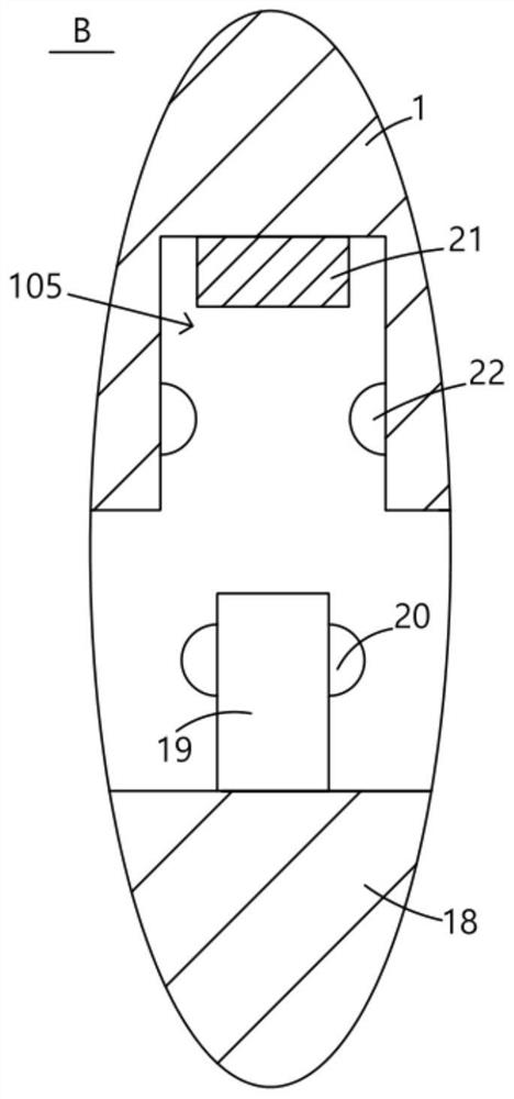
[0043] On the basis of Embodiment 1, this embodiment further specifically defines the buckle structure of "the pressing plate 18 can move up and down, and is snapped and fixed under the open box body 2": the upper part of the pressing plate 18 is fixed There is a clamping rod 19, the third protruding part 20 is fixedly arranged on the clamping rod 19, and the fourth protruding part 22 is fixedly provided on the inner wall of the groove 105, and the fourth protruding part 22 can carry out the third protruding part 20. The limit is fixed. When in use, the main mold 1 is lowered as a whole, and the pressure plate 18 will be restricted by the lower mold core below, and then passively pushed upward, so that the clamping rod 19 above the pressure plate 18 is inserted into the groove 105 until the first When the three protruding parts 20 are limited by the fourth protruding part 22, the pressing plate 18 at this time is fastened and fixed on the bottom of the open box body 2.
PUM
 Abstract
Description
Claims
Application Information