

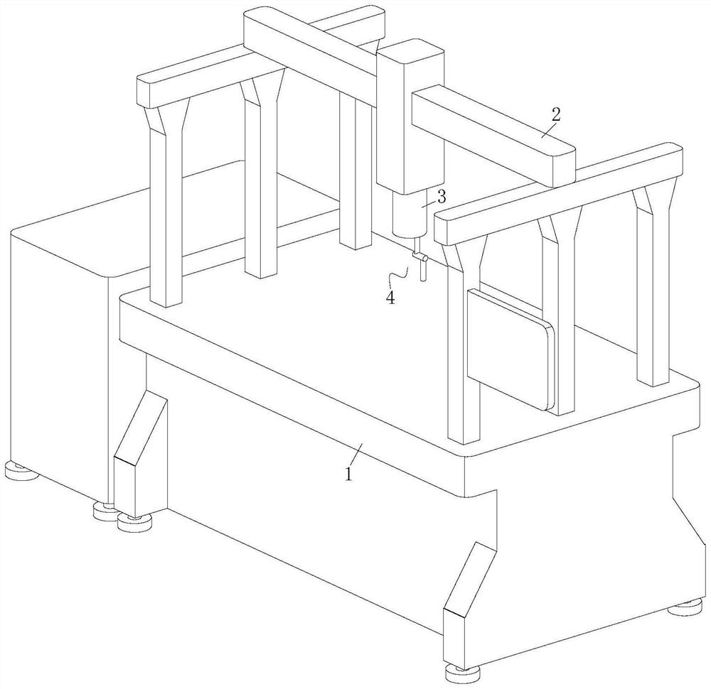
Longmen continuous galvanometer laser welding machine
A laser welding machine, gantry technology, applied in laser welding equipment, welding equipment, metal processing equipment and other directions, can solve the problems of vibration offset, danger, low efficiency of manual support and inconvenience, to enhance the scope of application and improve welding efficiency , Improve the effect of welding
- Summary
- Abstract
- Description
- Claims
- Application Information
AI Technical Summary
Problems solved by technology
Method used
Image

Examples
Embodiment approach
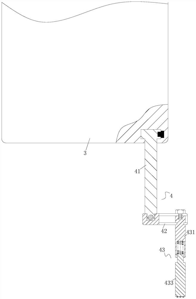
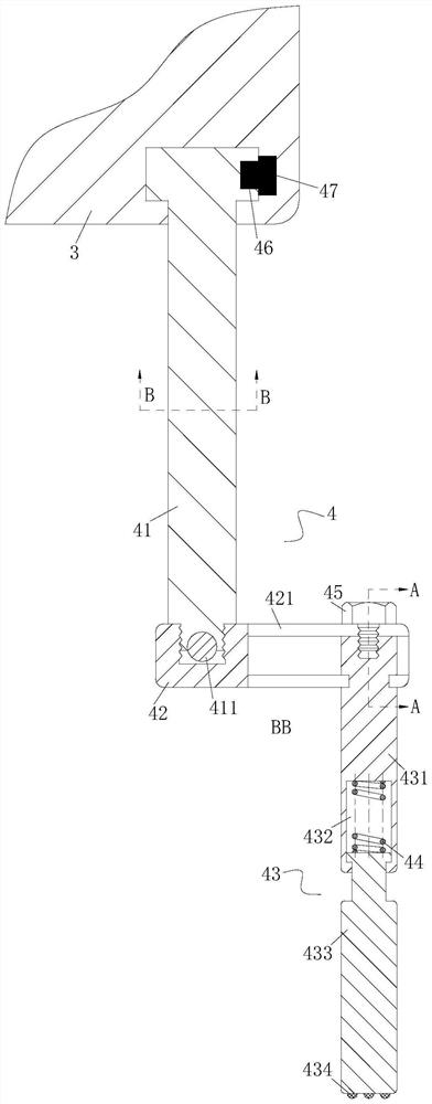
[0049] As an embodiment of the present invention, the supporting portion 4 includes
[0050] a rotating rod 41, the rotating rod 41 is placed vertically, and one end of the rotating rod 41 is rotatably connected to the lower end of the laser transmitter 3;
[0051] a connecting rod 42, the connecting rod 42 is placed horizontally, the connecting rod 42 is located at the lower part of the rotating rod 41 and is connected with the other end of the rotating rod 41;
[0052] pressing rod 43, the pressing rod 43 is placed vertically, the pressing rod 43 is located at the lower part of the connecting rod 42 and is connected to one end of the connecting rod 42;
[0053] The pressing rod 43 includes
[0054] an upper pressing rod 431, the upper end of the upper pressing rod 431 is connected to the connecting rod 42;
[0055] a lower pressing rod 433, the lower pressing rod 433 is located below the upper pressing rod 431 and is rotatably connected with the upper pressing rod 431;
...
PUM
 Abstract
Description
Claims
Application Information