
Physical cutting method for magnetic base material

A magnetic base material and cutting method technology, which is applied in the direction of stone processing tools, stone processing equipment, inductance/transformer/magnet manufacturing, etc., can solve the problems of not being suitable for large-scale production, low product qualification rate, and large chipping size. Achieve the effect of improving cutting quality, reducing cost and reducing edge chipping size

Pending Publication Date: 2022-03-25
XIAN INSTITUE OF SPACE RADIO TECH
View PDF0 Cites 2 Cited by
  • Summary
  • Abstract
  • Description
  • Claims
  • Application Information

AI Technical Summary

Problems solved by technology

Since the gyromagnetic ferrite material itself is porous, loose, and fragile, it is easy to cause the substrate to be broken by laser cutting, and the product qualification rate is low, so it is not suitable for large-scale production.
The physical cutting method in the prior art has slow cutting speed, large edge chipping size and low pass rate

Method used


Image

  • Physical cutting method for magnetic base material
  • Physical cutting method for magnetic base material
  • Physical cutting method for magnetic base material

Examples


Embodiment 1

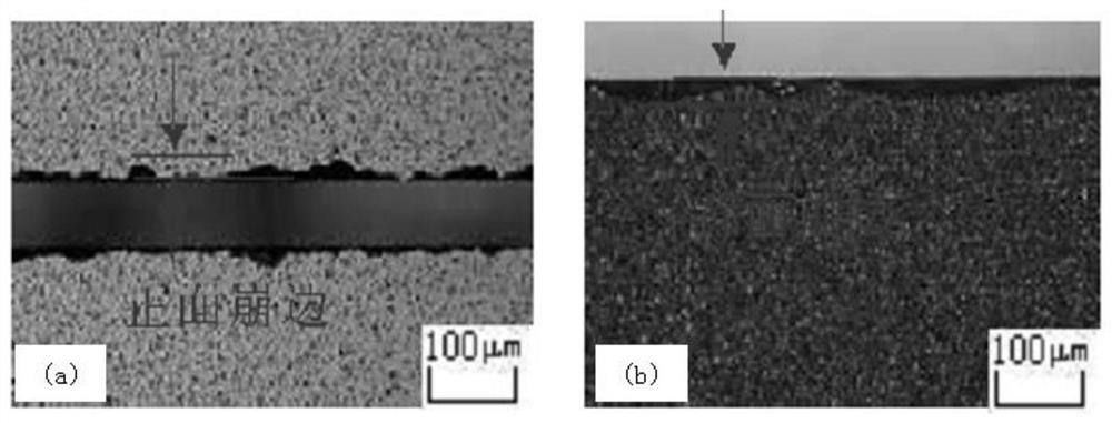
[0037] Based on a microwave ferrite substrate with a thickness of 0.4mm, adopt a cutting method, set different cutting parameters, measure the size of chipping on the front and back sides, and randomly measure 5 data as shown in Table 1. The cutting effect diagram is as follows figure 2 shown. When the tool is cutting, the spindle speed of the cutting machine is 28000 rpm, and the cutting depth is 0.42mm.

[0038] Table 1 The effect of different cutting speeds on the chipping of the front and back sides of the substrate

[0039]

Embodiment 2

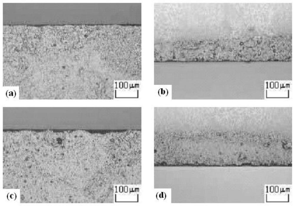
[0041] Based on a microwave ferrite substrate with a thickness of 1.0mm, adopt a cutting method, set different cutting parameters, measure the size of chipping on the front and back sides, and randomly measure 5 data as shown in Table 2. The cutting effect diagram is as follows image 3 shown. When the tool is cutting, the spindle speed of the cutting machine is 30,000 rpm, and the cutting depth is 1.02mm.

[0042]Table 2 The effect of different cutting speeds on the chipping of the front and back sides of the substrate

[0043]

Embodiment 3

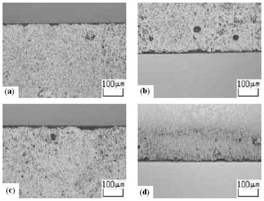
[0045] Based on a microwave ferrite substrate with a thickness of 1.5mm, adopt a one-time cutting method, set the cutting speed at 1.0mm / s, measure the edge chipping size of the front and back sides, and randomly measure 5 data as shown in Table 3. The cutting effect Figure such as Figure 4 shown. When the tool is cutting, the spindle speed of the cutting machine is 32000 rpm, and the cutting depth is 1.52mm.

[0046] Table 3 The effect of 1.0mm / s cutting speed on the edge chipping of the front and back of the substrate

[0047]


PUM

PropertyMeasurementUnit
diameteraaaaaaaaaa
thicknessaaaaaaaaaa
thicknessaaaaaaaaaa

Abstract

The invention discloses a physical cutting method for a magnetic base material, which is used for cutting microwave ferrite substrates with different thicknesses, and the optimal range of process cutting parameters is as follows: the rotating speed of a main shaft of a cutting machine is 25,000-35,000 r / min; the cutting speed is 1.0 to 5.0 mm / min; the cutting depth is d + 0.01 mm-d + 0.03 mm of the thickness of the magnetic base material, the number of times of cutting is 1-2, or the number of times of cutting is increased according to the thickness of the base material, a circular cutter made of a resin diamond material is adopted, and the cutting temperature is controlled within the range of 21 + / -1 DEG C. According to the invention, the size of broken edges is reduced, the number of broken chips is small, the qualified rate is high, the chip discharging speed is high, and batch and large-scale production of microwave ferrite devices can be realized.

Description

technical field [0001] The invention relates to a physical cutting method for microwave ferrite materials, which belongs to the field of mechanical processing of ceramic materials. Background technique [0002] Gyromagnetic ferrite, also known as microwave ferrite, is a magnetic substrate suitable for microwave frequency bands. Various microwave devices have been developed using its gyromagnetic properties. Due to its small size, light weight, less consumables, and easy integration, microwave ferrite devices play an important role in many civil and military equipment such as communication stations, satellites, and radars. The survey of market demand at home and abroad shows that for a long period of time in the future, the demand for microwave ferrite devices in the field of wireless communication will increase day by day. How to produce microwave ferrite devices in high efficiency and in large quantities to meet The increasingly urgent market demand is one of the technical...

Claims


Application Information

Patent Timeline
Patent Type & Authority Applications(China)
IPC IPC(8): B28D1/24B28D7/02H01F41/02
CPCB28D1/24B28D7/02H01F41/02
Inventor 王蓉董作典华熙李婧宋燕唐旭陈娜
Owner XIAN INSTITUE OF SPACE RADIO TECH
Learn More