
Transfer equipment for anti-collision carrying of medicament

An anti-collision and pharmaceutical technology, applied in the direction of transportation and packaging, containers to prevent mechanical damage, rigid containers, etc., can solve problems such as test tube fragmentation, and achieve the effects of firm fixation, stable removal, and convenient operation

Pending Publication Date: 2022-03-25
甘伟华
View PDF0 Cites 0 Cited by
  • Summary
  • Abstract
  • Description
  • Claims
  • Application Information

AI Technical Summary

Problems solved by technology

[0005] In order to overcome the disadvantage that the existing medicament transfer device cannot fix the test tube during the transportation of the test tube, which will cause the test tube to collide with the lower gasket during the transportation and cause the test tube to be broken. During the transportation process, the test tubes containing the medicines can be clamped to avoid collisions

Method used


Image

  • Transfer equipment for anti-collision carrying of medicament
  • Transfer equipment for anti-collision carrying of medicament
  • Transfer equipment for anti-collision carrying of medicament

Examples


Embodiment 1

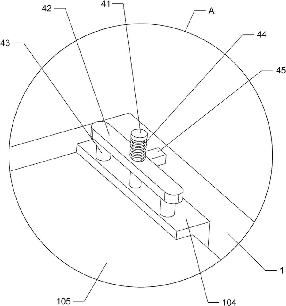
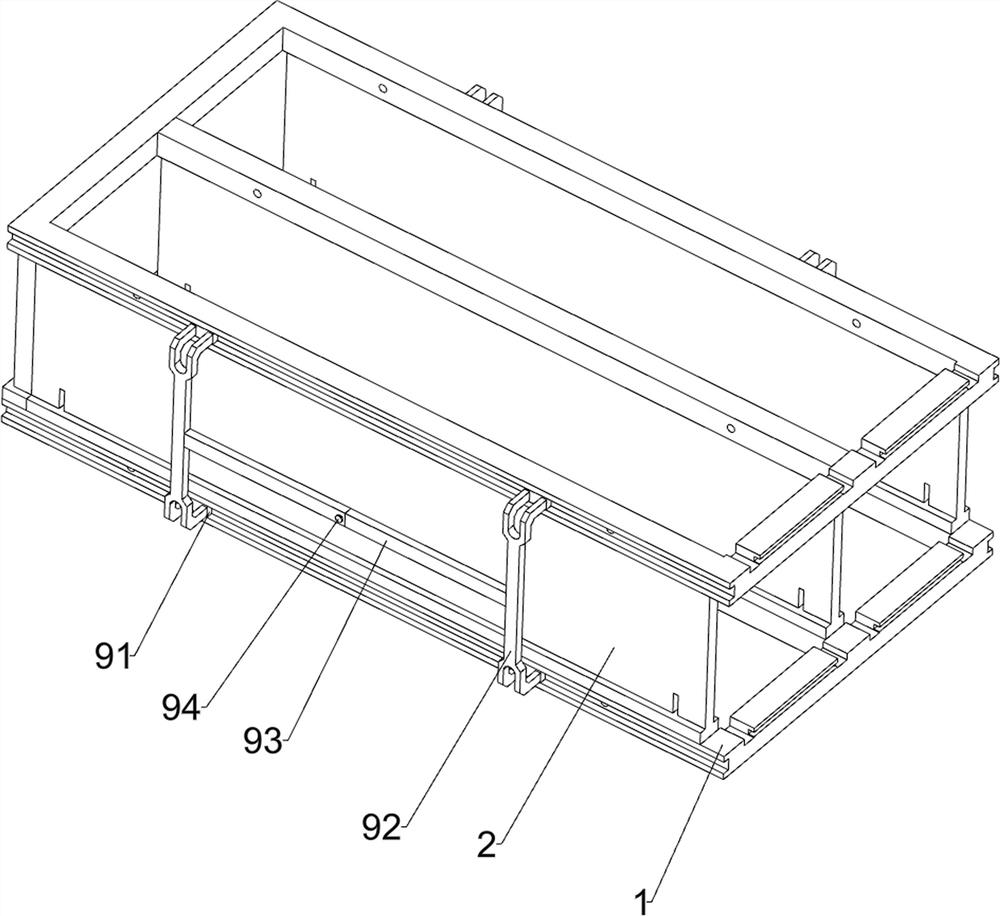
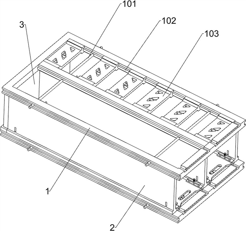
[0037] A transshipment device for anti-collision loading of medicaments, referring to Figure 1-Figure 8As shown, it includes a transfer frame 1, a first isolation plate 2, a second isolation plate 3, a fixed shaft 101, a guide rail 102, a bottom plate 103, a limit plate 104, a backing plate 105, a lower gasket 106, a bracket 107, and a fixing mechanism 4 and the transfer mechanism 5, the right side of the second isolation plate 3 is connected up and down symmetrically with the transfer frame 1 through the mortise and tenon structure, and three first isolation plates 2 are evenly connected between the transfer frames 1 through the mortise and tenon structure, and the transfer frame 1 is about Both sides are slidably provided with fixed shafts 101, and the fixed shafts 101 are slidably connected with the first isolation plate 2. A group of guide rails 102 are provided by welding on the front and rear sides of the transfer frame 1, and the number of each group of guide rails 102 ...

Embodiment 2

[0042] On the basis of embodiment 1, refer to figure 1 , Figure 9 and Figure 10 As shown, a supporting mechanism 6 is also included, and the supporting mechanism 6 plays a supporting role when the backing plate 105 is taken out so as to avoid toppling over. The supporting mechanism 6 includes a hinged rod 61, a third spring 62, a top block 63, and a first mounting block 64 , cross bar 65, the 4th spring 66, wedge block 67 and Cato 68, the front and back symmetrical rotation type of lower side transfer frame 1 right side is provided with a group of articulated rods 61, and the number of every group of articulated rods 61 is 2 and is arranged symmetrically front and back, A third spring 62 is connected between the front and rear sides of the hinged rod 61 and the lower transfer frame 1. The third spring 62 is a torsion spring. The top of the hinged rod 61 is provided with a top block 63 by welding. The front and rear symmetry of the right side is provided with a group of fir...


PUM


Abstract

The invention relates to medicament transfer equipment, in particular to transfer equipment for medicament anti-collision carrying. According to the transfer equipment for anti-collision carrying of the medicament, in the medicament transportation process, test tubes filled with the medicament can be clamped, and collision is avoided. Transfer equipment for anti-collision carrying of medicaments comprises transfer frames, first isolation plates, second isolation plates, fixing shafts, guide rails and the like, the transfer frames are vertically and symmetrically clamped to the right sides of the second isolation plates, the three first isolation plates are evenly clamped between the transfer frames, and the fixing shafts are slidably arranged on the left sides and the right sides of the transfer frames. The fixing shaft is slidably connected with the first isolation plate, and the front side and the rear side in the transfer frame are each provided with a set of guide rails. The supporting blocks can bear the bottoms of test tubes filled with medicaments, and the anti-skid blocks clamp the upper sides of the test tubes, so that the test tubes are separated and are placed firmly, and damage caused by mutual collision between the test tubes in the medicament transportation process can be prevented.

Description

technical field [0001] The invention relates to a drug transfer device, in particular to a transfer device for anti-collision loading of drugs. Background technique [0002] Medicaments refer to substances used to prevent, treat, and diagnose human diseases, purposefully regulate human physiological functions, and stipulate indications or functional indications, usage and dosage. Medicaments are usually stored in storage rooms, and when needed, they can be used The medicine needs to be taken out for transportation, so the medicine needs to be used. [0003] Existing drug transfer devices usually include a backing plate, lower gaskets and brackets. Four lower gaskets are arranged on the top of the backing plate, and three brackets are evenly arranged on the lower part of the lower gaskets. The test tube is placed in the lower gasket, and the supporting block can accept the bottom of the test tube, and then the backing plate can be carried to move, so as to transfer the medic...

Claims


Application Information

Patent Timeline
Patent Type & Authority Applications(China)
IPC IPC(8): B65D6/08B65D25/02B65D25/10B65D81/05B65D25/24
CPCB65D7/14B65D11/14B65D25/02B65D25/10B65D81/05B65D25/24
Inventor 甘伟华
Owner 甘伟华
Learn More