Eureka AIR delivers breakthrough ideas for toughest innovation challenges, trusted by R&D personnel around the world.

Electro-hydraulic integrated control holding clamp lifting turnover device and control method

A flipping device and clamping technology, which is applied in the field of clamping lifting and flipping devices, can solve the problems of being unable to apply to the automatic processing of workpieces, etc., and achieve the effect of wide application range

Active Publication Date: 2022-03-25
FUJIAN POLYTECHNIC OF INFORMATION TECH
View PDF11 Cites 2 Cited by
  • Summary
  • Abstract
  • Description
  • Claims
  • Application Information

AI Technical Summary

Problems solved by technology

[0003] Although the existing CN 104591065 A discloses a safe and reliable bucket dumping device, the clamping of this device adopts a fixed hoop-type clamping mechanism, and the turnover adopts a manual gear box structure, which cannot be applied to workpieces. automated processing
[0004] In CN 207106975 U, a yarn ball resetting and turning device is disclosed. Although this device can realize clamping and lifting, the axial turning mainly driven by a motor is not applicable to the horizontal turning of the entire workpiece.
And flipping requires another set of flipping power units

Method used


Image

  • Electro-hydraulic integrated control holding clamp lifting turnover device and control method
  • Electro-hydraulic integrated control holding clamp lifting turnover device and control method
  • Electro-hydraulic integrated control holding clamp lifting turnover device and control method

Examples


Embodiment 1

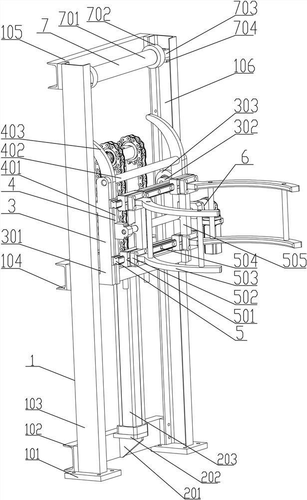
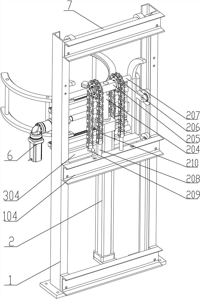
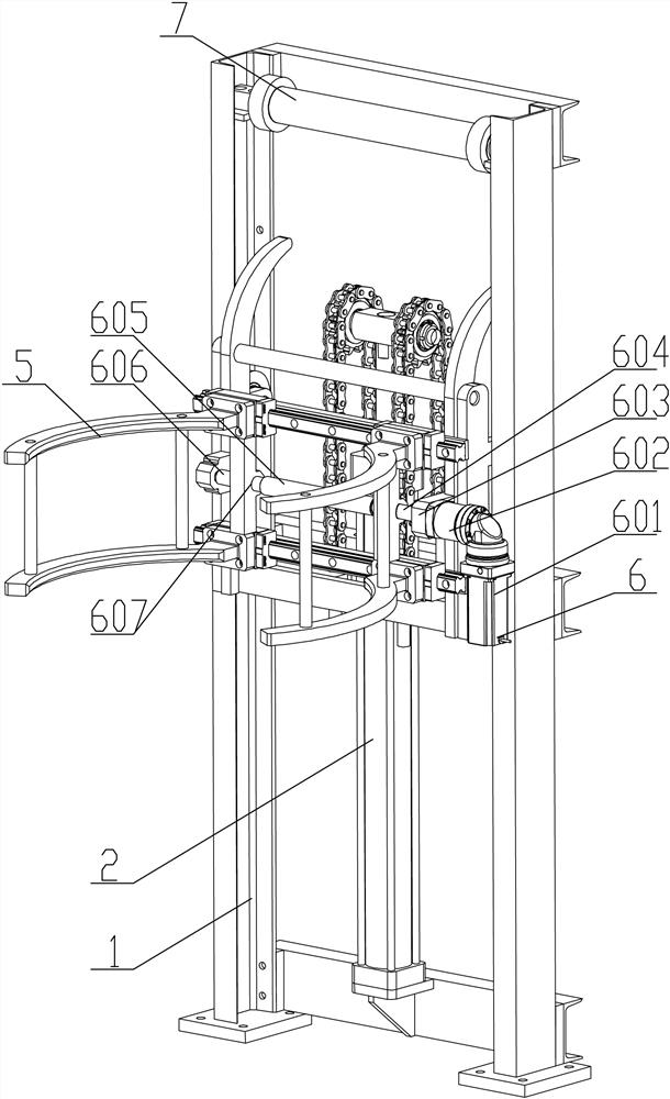
[0046] see Figure 1-5, an electro-hydraulic integrated lifting and flipping device, which includes a frame structure 1 for supporting the entire device. The frame structure 1 is equipped with a lifting carriage structure 3 through lifting and sliding. The lifting slide The frame structure 3 is connected with the chain lifting device 2 used to drive its lifting; the lifting carriage structure 3 is rotated and fitted with an overturning frame structure 4; the overturning frame structure 4 is connected with the overturning guide fixed on the top of the frame structure 1 Mechanism 7 cooperates; The outer wall of the flip frame structure 4 is equipped with a clamping arm mechanism 5 for clamping the workpiece, and the clamping arm mechanism 5 is connected with a clamping power device 6 for driving its clamping. This device can be used for the clamping of the workpiece. After clamping, it can realize the height adjustment control of its height, and can automatically turn over after...

Embodiment 2

[0056] The control method of the clamp lifting and turning device controlled by electro-hydraulic integration includes the following steps:

[0057] Step 1, start the chain lifting device 2, and move the lifting carriage structure 3 down to the height of the workpiece to be clamped;

[0058] Step 2, start the clamping power device 6, drive the reducer 602 through the servo motor 601, drive the first screw mandrel 604 and the second screw mandrel 606 through the reducer 602, and synchronously drive the arms 503 of the clamping arm mechanism 5 to move toward each other, Realize the clamping of the workpiece; wherein, during the clamping process, the clamping force is detected by the pressure sensor 9, and when the clamping force reaches the set value, the pressure sensor 9 transmits the pressure signal to the controller 8, and is controlled by the controller 8 The motor driver 11 drives the servo motor 601 to stop rotating by the motor driver 11;

[0059] Step 3: After the clam...


PUM


Abstract

The invention provides an electro-hydraulic integrated control clamping lifting turnover device and a control method, the electro-hydraulic integrated control clamping lifting turnover device comprises a rack structure used for supporting the whole device, the rack structure is matched with a lifting sliding frame structure in a lifting sliding mode, and the lifting sliding frame structure is connected with a chain type lifting device used for driving the lifting sliding frame structure to ascend and descend; the lifting sliding frame structure is rotationally matched with an overturning frame structure. The turnover frame structure is matched with a turnover guide mechanism fixed at the top end of the rack structure; a clamping arm mechanism used for tightly holding a workpiece is installed on the outer side wall of the overturning frame structure and connected with a clamping power device used for driving the clamping arm mechanism to clamp the workpiece. The device can be used for clamping a workpiece, lifting adjustment control of the height of the device can be achieved after clamping, the device can be automatically turned over after the height reaches a certain height, and then adjustment of the turning angle of the device is achieved.

Description

technical field [0001] The invention belongs to the field of lifting and turning equipment, and in particular relates to a clamp lifting and turning device and a control method controlled by electro-hydraulic integration. Background technique [0002] In the development process of non-standard automation equipment, it is necessary to use the workpiece to hold the lifting mechanism, and after the workpiece rises to a certain height, it needs to be turned over to facilitate its processing. [0003] Although the existing CN 104591065 A discloses a safe and reliable bucket dumping device, the clamping of this device adopts a fixed hoop-type clamping mechanism, and the turnover adopts a manual gear box structure, which cannot be applied to workpieces. automated processing. [0004] Disclosed in CN 207106975 U is a kind of resetting and overturning device for yarn clusters. Although this device can realize clamping and lifting, the motor-driven axial overturning mainly used in it...

Claims


Application Information

Patent Timeline
Patent Type & Authority Applications(China)
IPC IPC(8): B65G47/248B65G47/90
CPCB65G47/248B65G47/902
Inventor 何用辉卓书芳程千晟郭崇光沈子弘苏小宝
Owner FUJIAN POLYTECHNIC OF INFORMATION TECH
Why Eureka
Eureka Blog
Learn More