Warping machine and control method thereof
A warping machine and warp beam technology, applied in the field of textile machinery, can solve the problems of reducing the warping machine speed and production capacity, and achieve the effects of reducing frictional resistance, improving efficiency and ensuring uniformity
- Summary
- Abstract
- Description
- Claims
- Application Information
AI Technical Summary
Problems solved by technology
Method used
Image
Examples
Embodiment 1
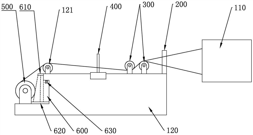
[0047] Such as figure 1 As shown, the embodiment of the present application provides a warping machine, including: a creel 110, on which a number of yarn bobbins are placed for unwinding; a front reed 200, the front reed 200 makes each yarn after unwinding mutually Separation; yarn guiding roller 300, yarn guiding roller 300 pulls the yarn to move; telescopic reed structure 400, telescopic reed structure 400 controls yarn arrangement evenly; warp beam 500, warp beam 500 winds all yarns evenly; detection mechanism 600 , the detection mechanism 600 adopts image forming to detect the condition of the peripheral surface formed by the yarn winding on the warp beam 500; wherein, the front reed 200, the guide roller 300, the telescopic reed structure 400, and the warp beam 500 are all installed on the warping table 120 , A steering roller 121 is installed between the warp beam 500 and the telescopic reed structure 400 .
[0048] A number of yarn bobbins are placed on the creel 110. ...
Embodiment 2
[0050] Such as figure 1 As shown, the embodiment of the present application provides a warping machine. In addition to the above-mentioned technical features, the detection mechanism 600 further includes: an illumination device 610; a projection board 620; a photographing device 630; 1. The projection board 620 is installed on the warping table 120 in turn, the lighting device 610 and the photographing device 630 are placed on one side of the warp axis 500, the projection board 620 is placed on the other side of the warp shaft 500, and the lighting device 610 generates light to irradiate the warp beam. Through the gap between the table 120 and the warp beam 500, and projected onto the projection board 620, the photographing device 630 captures and saves the illuminated image on the projection board 620 and transmits it to the processor for analysis.
[0051]The illuminating device 610 emits light, irradiates between the warp beam 500 and the warping table 120, and projects a l...
Embodiment 3
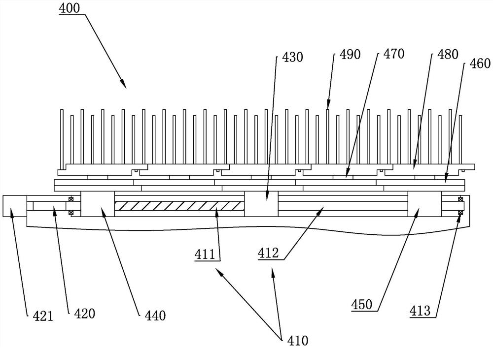
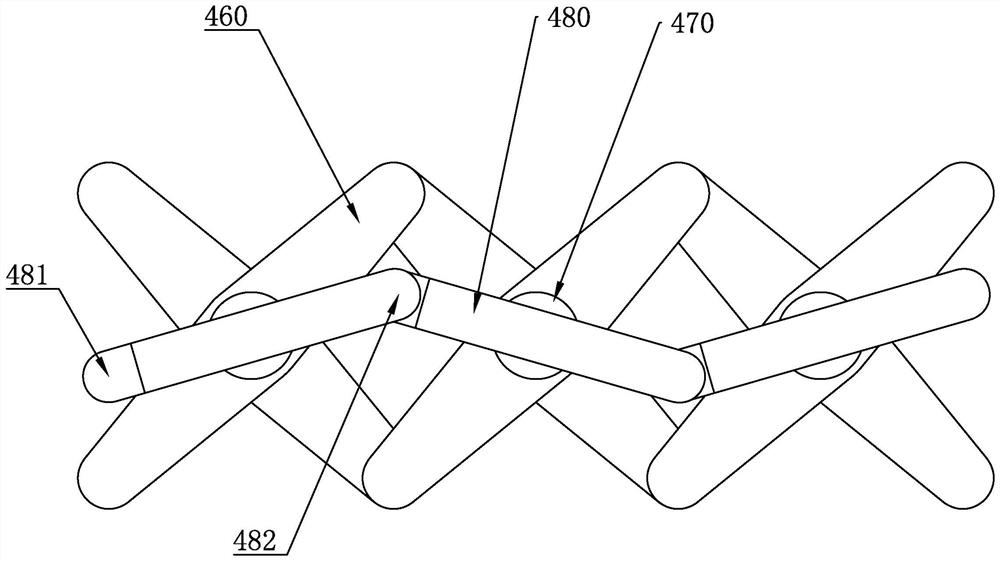
[0053] Such as figure 2 , image 3 As shown, the embodiment of the present application provides a warping machine. In addition to the above technical features, further, the telescopic reed structure 400 includes: a screw 410, one side of the screw 410 is provided with a threaded part 411, and the other side of the screw 410 is There is a sliding part 412, the screw rod 410 is installed on the warping table 120, and thrust bearings 413 are installed at both ends of the screw rod 410; the transmission shaft 420, the transmission shaft 420 is connected with the screw rod 410; the fixed bearing seat 430, the fixed bearing seat 430 Placed on the screw 410, and placed between the threaded part 411 and the sliding part 412; the threaded seat 440, the threaded seat 440 is placed on the screw 410 and fits with the threaded part 411; the sliding seat 450, the sliding seat 450 is placed on the screw 410 and adapt to the sliding part 412; the hinge 460, the hinge 460 is installed on the...
PUM
 Abstract
Description
Claims
Application Information
 - R&D
- Intellectual Property
- Life Sciences
- Materials
- Tech Scout
- Unparalleled Data Quality
- Higher Quality Content
- 60% Fewer Hallucinations
Browse by: Latest US Patents, China's latest patents, Technical Efficacy Thesaurus, Application Domain, Technology Topic, Popular Technical Reports.
© 2025 PatSnap. All rights reserved.Legal|Privacy policy|Modern Slavery Act Transparency Statement|Sitemap|About US| Contact US: help@patsnap.com


