Self-centering steel frame column base joint structure utilizing sliding friction to dissipate energy

A technology of friction energy consumption and column foot joints, which is applied in the field of steel frame column feet, can solve the problems of single dynamics, poor flexibility of the overall structure, and low sliding friction energy consumption

Pending Publication Date: 2022-03-25
WUHAN UNIV OF SCI & TECH
View PDF1 Cites 0 Cited by
  • Summary
  • Abstract
  • Description
  • Claims
  • Application Information

AI Technical Summary

Problems solved by technology

[0002] The design and construction of anti-seismic buildings have attracted more and more attention. According to modern anti-seismic design theory, even if there is no catastrophic collapse of buildings under the action of earthquakes, the cost of repairing or demolishing them is relatively low. It is very huge. In order to reduce the loss after the earthquake, how to reduce the residual deformation of steel structures has become a research hotspot in today's society. The retrieved application number is 201922454578.5, which discloses a self-centering steel frame column that uses sliding friction to dissipate energy. The foot node includes a steel column, a reinforced steel plate and a foundation beam, the steel column includes a left flange plate, a right flange plate and a column web, and the left side and the right side of the column web respectively fix the left flange plate and the right w

Method used


Image

  • Self-centering steel frame column base joint structure utilizing sliding friction to dissipate energy
  • Self-centering steel frame column base joint structure utilizing sliding friction to dissipate energy
  • Self-centering steel frame column base joint structure utilizing sliding friction to dissipate energy

Examples


Embodiment Construction

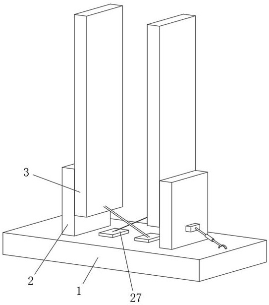
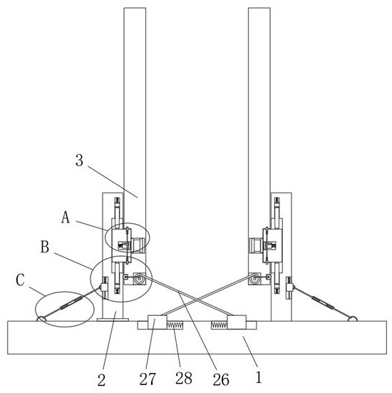
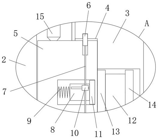
[0005] The implementation mode of the present invention is illustrated by specific specific examples below, and those who are familiar with this technology can easily understand other advantages and effects of the present invention from the contents disclosed in this description. Obviously, the described embodiments are a part of the present invention. , but not all examples. Based on the embodiments of the present invention, all other embodiments obtained by persons of ordinary skill in the art without making creative efforts belong to the protection scope of the present invention. refer to Figure 1-5, a self-centering steel frame column foot joint structure utilizing sliding friction energy dissipation, comprising a column foot bottom plate 1, two column foot sub-plates 2 and two column foot main plates 3, and two column foot sub-plates 2 are all slidably installed on the top of the column base plate 1, the column base main board 3 is arranged on the corresponding column b...


PUM


Abstract

The invention belongs to the field of steel frame column bases, particularly relates to a self-centering steel frame column base joint structure utilizing sliding friction to consume energy, and aims at solving the problems that an existing steel frame column base joint structure is single in dynamic nature, low in energy consumption of sliding friction, low in utilization rate of the sliding friction and poor in flexibility of an overall structure. According to the technical scheme, the column base comprises a column base bottom plate, two column base auxiliary plates, two column base main plates, two node installation assemblies, two side edge sliding assemblies and two bottom sliding assemblies, the two column base auxiliary plates are both installed on the top of the column base bottom plate in a sliding mode, the column base main plates are arranged on the corresponding column base auxiliary plates, and the two node installation assemblies are arranged on the two side edge sliding assemblies. And the node mounting assemblies are arranged on the corresponding column foot auxiliary plates. The steel frame column base joint structure is flexible in dynamic nature, high in energy consumption of sliding friction, high in utilization rate of the sliding friction and good in flexibility of the whole structure.

Description

technical field [0001] The invention relates to the field of steel frame column feet, in particular to a self-centering steel frame column foot node structure utilizing sliding friction to dissipate energy. Background technique [0002] The design and construction of anti-seismic buildings have attracted more and more attention. According to modern anti-seismic design theory, even if there is no catastrophic collapse of buildings under the action of earthquakes, the cost of repairing or demolishing them is relatively low. It is very huge. In order to reduce the loss after the earthquake, how to reduce the residual deformation of steel structures has become a research hotspot in today's society. The retrieved application number is 201922454578.5, which discloses a self-centering steel frame column that uses sliding friction to dissipate energy. The foot node includes a steel column, a reinforced steel plate and a foundation beam, the steel column includes a left flange plate,...

Claims


Application Information

Patent Timeline
IPC IPC(8): E04C3/32E04B1/38E04B1/98E04H9/02
CPCE04C3/32E04B1/38E04B1/98E04H9/021
Inventor 谢琳琳
Owner WUHAN UNIV OF SCI & TECH
Why Eureka
Try Eureka