Semi-combined pressure ring sensor and design method thereof

A pressure ring and sensor technology, applied in the field of semi-combined pressure ring sensor and its design, can solve the problems of difficult to achieve compression volume, lack of installation space, and great impact on accuracy, so as to reduce the cost of defective products and mass production efficiency High and durable effect

Pending Publication Date: 2022-03-25
GUILIN UNIVERSITY OF TECHNOLOGY
View PDF0 Cites 1 Cited by
  • Summary
  • Abstract
  • Description
  • Claims
  • Application Information

AI Technical Summary

Problems solved by technology

The combined pressure ring that disperses the force through the pressure ring has solved the problem that the eccentric load state has a great influence on the accuracy, but in the application environment of narrow spaces such as single-hole steel strands

Method used


Image

  • Semi-combined pressure ring sensor and design method thereof
  • Semi-combined pressure ring sensor and design method thereof
  • Semi-combined pressure ring sensor and design method thereof

Examples


Embodiment 1

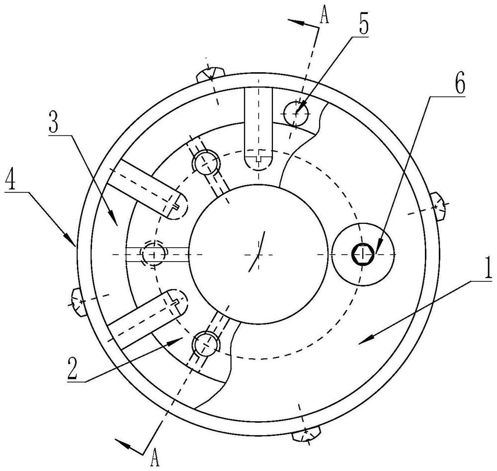
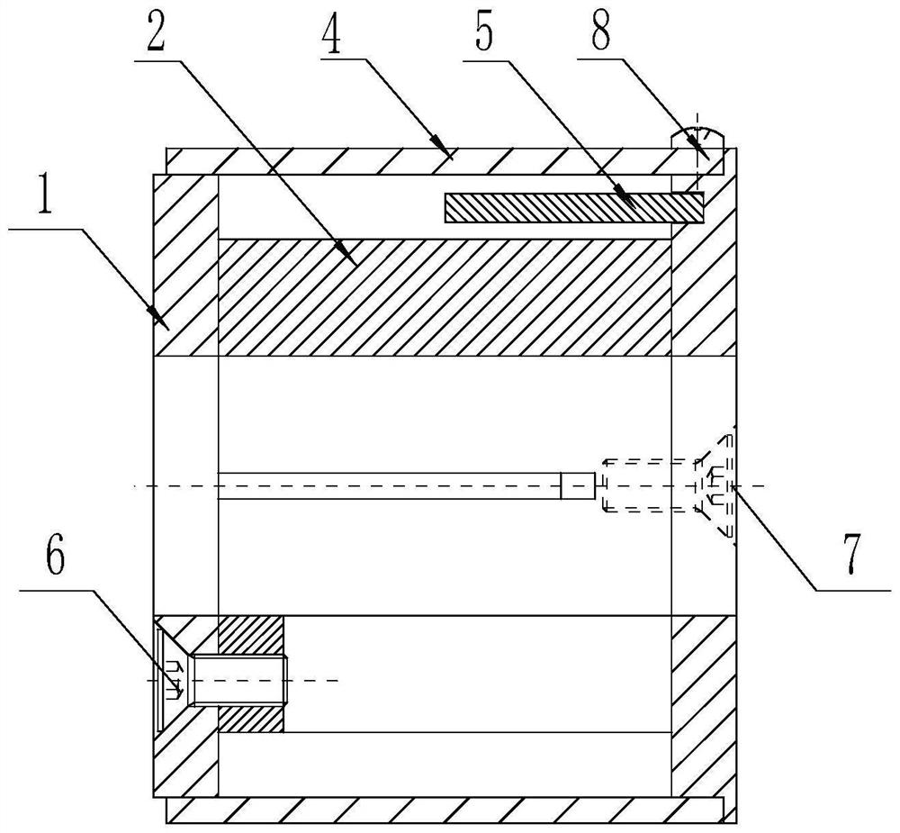
[0083] Figure 1-Figure 2 Disclosed in is a semi-combined pressure ring sensor, including an upper pressure plate 1, a pressure bearing ring 2, a lower pressure plate 3, an outer sleeve 4, and a temperature compensation column 5;

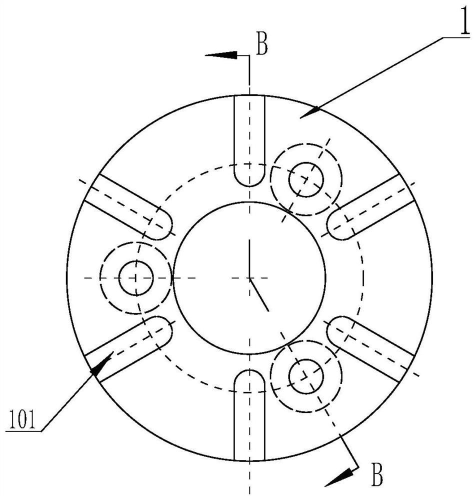
[0084] The upper pressure plate 1 is provided with three installation holes I102; the pressure bearing ring 2 is located in the outer sleeve 4, and the two ends of the pressure bearing ring 2 are respectively provided with three installation holes II204; the lower pressure plate 3 is provided with installation hole III 303, installation hole IV 304 and threaded hole 302; one end of the outer sleeve 4 is provided with installation hole V401. The number, position and size of the installation hole I102 of the upper platen 1 and the installation hole II204 at one end of the pressure ring 2 match, and the screw I6 connects the upper platen 1 and the pressure ring 2 tightly through the installation hole I102 and the installation hole II204 together; the ...

Embodiment 2

[0094] A semi-combined pressure ring sensor, the structure of which is basically the same as that of Embodiment 1, including an upper pressure plate 1, a pressure bearing ring 2, a lower pressure plate 3, an outer sleeve 4, and a temperature compensation column 5; the only difference is:

[0095] The distribution positions of the n=6 dividing seams 201 on the pressure bearing ring 2 are different, such as Figure 13-Figure 14 As shown, the distribution was ipsilateral.

Embodiment 3

[0097] A design method of a semi-combined pressure ring sensor, which is the design method of the semi-combined pressure ring sensor described in Embodiment 1 or Embodiment 2, which is to calculate the minimum pressure-bearing area and minimum outer diameter of the pressure-bearing ring respectively , the minimum height, and locate the measuring point groove Ⅰ; then design the supporting upper platen, lower platen, outer sleeve and temperature compensation column respectively, and obtain the minimum outer diameter and minimum height of the semi-combined pressure ring sensor, and complete the half-combination The design of pressure ring sensor.

[0098] The concrete steps of this method include:

[0099] S1. Calculation of the minimum pressure-bearing area of ​​the pressure-bearing ring:

[0100] Assume that the force of the actual use environment is F, and the number of measuring points required by the design is n, that is, the number of pressure-bearing areas is n. In order to...


PUM

PropertyMeasurementUnit
Ultimate tensile strengthaaaaaaaaaa
Rockwell hardnessaaaaaaaaaa

Abstract

The invention discloses a semi-combined pressure ring sensor and a design method thereof, and relates to a sensor and a design method thereof. The sensor comprises an upper pressing plate, a pressure bearing ring, a lower pressing plate and an outer sleeve; the outer sleeve is installed on the lower pressing plate, the pressure-bearing ring is located in the outer sleeve, and the two ends of the pressure-bearing ring are connected with the upper pressing plate and the lower pressing plate respectively. The pressure-bearing ring is provided with n dividing seams, the pressure-bearing ring is uniformly distributed into n pressure-bearing areas, the cross section shapes and areas of the pressure-bearing areas are the same, and each pressure-bearing area is provided with a working groove and a measuring point groove I; the measuring point groove I is located in the middle line of the bottom of the working groove and internally provided with a measuring point. The method comprises the following steps: respectively calculating the minimum pressure-bearing area, the minimum outer diameter and the minimum height of the pressure-bearing ring; and an upper pressing plate, a lower pressing plate, an outer sleeve and a temperature compensation column are respectively designed to obtain the minimum outer diameter and the minimum height of the sensor. The device has the advantages of being high in precision, good in unbalance loading resistance, suitable for being installed in a narrow space, excellent in environmental vibration resistance, good in durability, high in batch production efficiency and easy to apply and popularize.

Description

technical field [0001] The invention relates to a sensor and a design method thereof, in particular to a semi-combined pressure ring sensor and a design method thereof. Background technique [0002] In the context of the increasingly prominent safety issues of engineering structures such as buildings and structures, unlike previous detections, structural monitoring requires long-term effectiveness and stability on the basis of accuracy, which puts forward higher requirements for sensors. And standards, traditional energized sensors have been difficult to meet the requirements of structural intelligence monitoring in many applications. Optical fiber sensors have many advantages such as high durability, weather resistance, high sensitivity, anti-electromagnetic interference, long transmission distance and high stability. With the development of fiber optic sensing technology, fiber optic sensors are gradually favored by the civil engineering inspection and monitoring industry...

Claims


Application Information

Patent Timeline
IPC IPC(8): G01L1/24
CPCG01L1/246
Inventor 朱万旭刘丰荣覃荷瑛黄家柱张贺丽沈全喜苏泳旗
Owner GUILIN UNIVERSITY OF TECHNOLOGY
Why Eureka
Try Eureka