Supercharge Your Innovation With Domain-Expert AI Agents!

Flexible speed planning and displacement compensation method for laser cutting

A displacement compensation and laser cutting technology, applied in general control systems, program control, instruments, etc., can solve the problems of complex and cumbersome processes, inability to achieve efficient execution, etc., and achieve the effects of efficient execution, smooth and soft movements, and accurate precision.

Pending Publication Date: 2022-03-25
CENT SOUTH UNIV +1
View PDF2 Cites 0 Cited by
  • Summary
  • Abstract
  • Description
  • Claims
  • Application Information

AI Technical Summary

Problems solved by technology

[0005] However, the speed planning method disclosed in the above-mentioned patent is relatively traditional, and its specific process is very complicated and cumbersome, and cannot achieve efficient execution

Method used


Image

  • Flexible speed planning and displacement compensation method for laser cutting
  • Flexible speed planning and displacement compensation method for laser cutting
  • Flexible speed planning and displacement compensation method for laser cutting

Examples


Embodiment 1

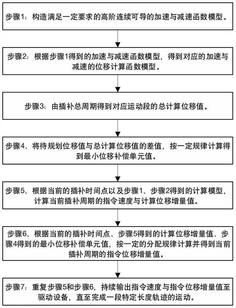
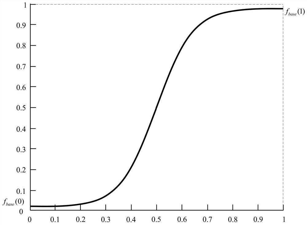
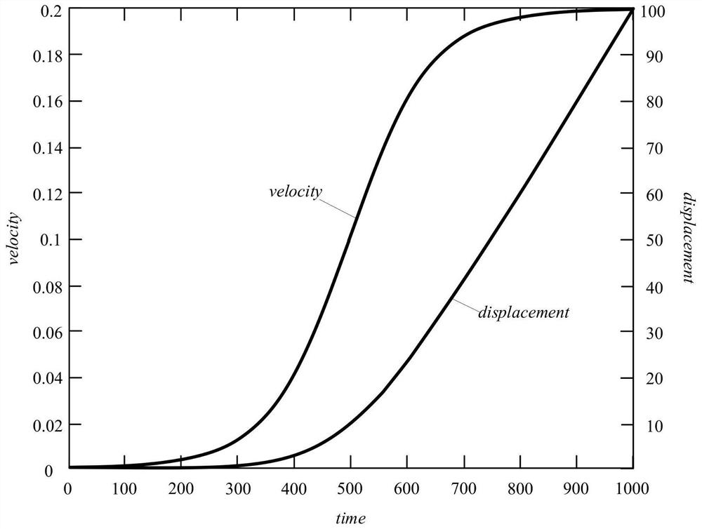
[0039] figure 1 Execution flow chart for the steps of the present invention, figure 2 It is a schematic diagram of the basic speed curve and its basic parameters of the present invention, image 3 Be the speed, displacement curve figure in the embodiment of the present invention, Figure 4 Be the acceleration graph in the embodiment of the present invention, as figure 1 , figure 2 , image 3 and Figure 4 A flexible speed planning and displacement compensation method for laser cutting is shown, and its specific implementation includes the following steps:

[0040] Step 1.1, construct the acceleration and deceleration function model, and ensure that the two functions meet certain requirements, namely: domain x∈[0,1], value range y∈[0,1], first define the acceleration and deceleration basic functions: where a is a calculation constant.

[0041] Step 1.1.1, constructing the acceleration function model: the acceleration function model in step S1 adopts

[0042] Step 1...

Embodiment 2

[0083] figure 1 Execution flow chart for the steps of the present invention, figure 2 It is a schematic diagram of the basic speed curve and its basic parameters of the present invention, image 3 Be the speed, displacement curve figure in the embodiment of the present invention, Figure 4 Be the acceleration graph in the embodiment of the present invention, as figure 1 , figure 2 , image 3 and Figure 4 A flexible speed planning and displacement compensation method for laser cutting is shown, and its specific implementation includes the following steps:

[0084] Step 1.1, construct the acceleration and deceleration function model, and ensure that the two functions meet certain requirements, namely: domain x∈[0,1], value range y∈[0,1], first define the acceleration and deceleration basic functions: where a is a calculation constant.

[0085] Step 1.1.1, constructing the acceleration function model: the acceleration function model in step S1 adopts

[0086] Step 1...

Embodiment 3

[0127] figure 1 Execution flow chart for the steps of the present invention, figure 2 It is a schematic diagram of the basic speed curve and its basic parameters of the present invention, image 3 Be the speed, displacement curve figure in the embodiment of the present invention, Figure 4 Be the acceleration graph in the embodiment of the present invention, as figure 1 , figure 2 , image 3 and Figure 4 A flexible speed planning and displacement compensation method for laser cutting is shown, and its specific implementation also includes the following steps:

[0128] First, consider an accelerated motion process, assuming the initial velocity v s =0, the target speed v tar =0.2, the maximum acceleration A during the acceleration process a =0.0007, the displacement value S to be planned plan =100.

[0129] Step 1. Construct a high-order continuously differentiable acceleration and deceleration function model that meets certain requirements. Preferably, the accele...


PUM


Abstract

The invention relates to the technical field of numerical control machining, in particular to a flexible speed planning and displacement compensation method for laser cutting, which comprises the following steps of: firstly, constructing a high-order continuous derivable acceleration function model and a high-order continuous derivable deceleration function model; according to the obtained acceleration function model and the deceleration function model, obtaining a corresponding acceleration displacement calculation function model and a deceleration displacement calculation function model; obtaining a total calculation displacement value of the corresponding motion section according to the total interpolation period; and calculating a difference value between the to-be-planned displacement value and the total calculated displacement value according to a rule to obtain a minimum displacement compensation unit value. The speed function construction method provided by the invention has a high-order continuous derivable characteristic, by combining with a displacement compensation method, strong vibration or track distortion cannot be brought to the machine tool while accurate movement displacement is ensured, the requirements of flexible movement and smooth cutting of the machine tool can be met, and compared with a traditional speed planning method, the speed planning method provided by the invention has the advantages that the speed planning efficiency is improved. The method has the advantages of simple process and efficient execution.

Description

technical field [0001] The invention relates to the technical field of numerical control processing, in particular to a flexible speed planning and displacement compensation method for laser cutting. Background technique [0002] At present, laser cutting CNC machine tools have been widely used in the processing of high-precision and complex parts. For example, the invention patent CN201910723345.2 discloses a laser cutting system and its cutting method, including a laser cutting head, and an LED light is set on the laser cutting head ; Workbench, the workbench is set directly below the laser cutting head, used to carry the profile to be cut; detection device, the detection device is set on the upper surface of the workbench, used to detect the appearance and structural feature information of the profile to be cut; control device, laser The cutting head is connected to the control device through a mechanical arm, and the detection device is connected to the control device th...

Claims


Application Information

Patent Timeline
IPC IPC(8): G05B19/404
CPCG05B19/404G05B2219/32063
Inventor 但汉兵余文辉宋俊杰刘新赫宇粟梅
Owner CENT SOUTH UNIV
Features
  • R&D
  • Intellectual Property
  • Life Sciences
  • Materials
  • Tech Scout
  • Unparalleled Data Quality
  • Higher Quality Content
  • 60% Fewer Hallucinations
Learn More