Rotor structure of asynchronous motor

A rotor structure, asynchronous motor technology, applied in the manufacture of motor generators, stator/rotor body, magnetic circuit shape/style/structure, etc., can solve problems such as assembly process difficulties, save time and labor in assembly, and reduce process difficulty Effect

Pending Publication Date: 2022-03-25
CRRC YONGJI ELECTRIC CO LTD
View PDF6 Cites 0 Cited by
  • Summary
  • Abstract
  • Description
  • Claims
  • Application Information

AI Technical Summary

Problems solved by technology

[0003] The present invention provides a new asynchronous motor rotor structure in order to solve the problem that the existing asynchronous motor rotor structure is difficult to assemble when the shaft is relatively long

Method used


Image

  • Rotor structure of asynchronous motor
  • Rotor structure of asynchronous motor
  • Rotor structure of asynchronous motor

Examples


Embodiment 1

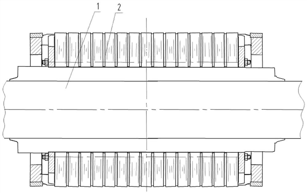
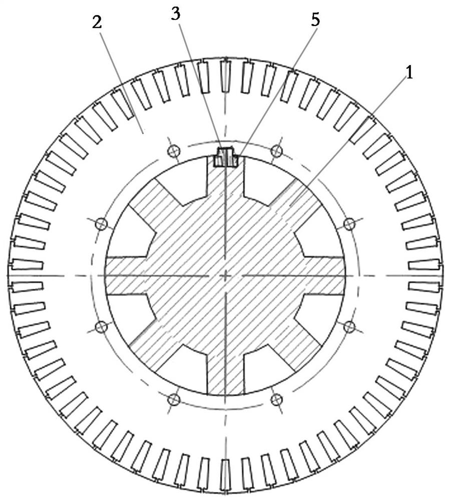
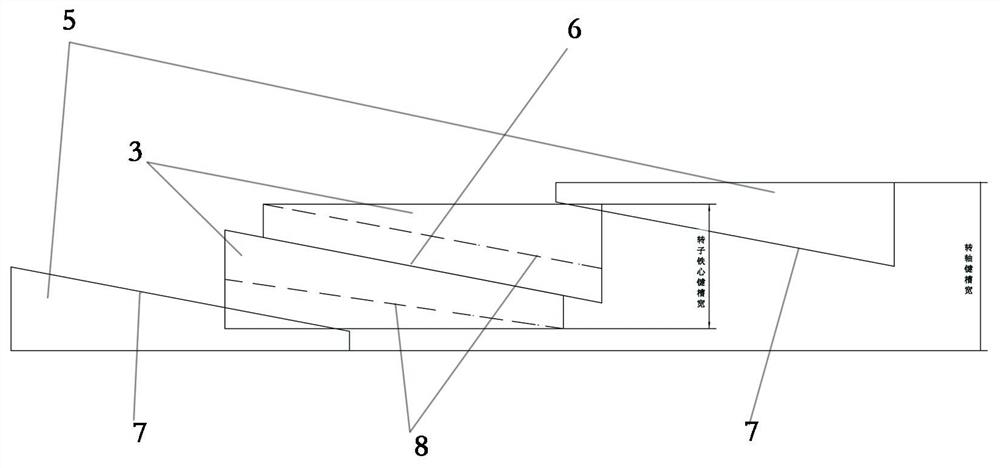
[0020] Embodiment one: if Figure 1 to Figure 7 As shown, an asynchronous motor rotor structure includes a rotating shaft 1 and a rotor core 2. Both the rotor core 2 and the rotating shaft 1 are provided with axially penetrating key grooves, and the width of the key groove on the rotor core 2 is smaller than that on the rotating shaft 1. It includes two first wedge-shaped keys 3 located in the space formed by the key groove of the rotor core 2 and the key groove of the rotating shaft 1 and a second wedge-shaped key 5 located in the key groove of the rotating shaft 1. The two first wedge-shaped keys 3 and the second wedge-shaped key The height directions of 5 are all arranged axially along the rotating shaft 1. The height direction is arranged axially along the rotating shaft 1, that is, the arrangement direction of the height of the first wedge-shaped key 3 is consistent with the axial direction of the rotating shaft 1 and its cross-section is a right-angled trapezoid. The firs...

Embodiment 2

[0026] Embodiment two: if Figure 4 to Figure 7As shown, a rotor structure of an asynchronous motor includes a rotating shaft 1 and a rotor core 2. Both the rotor core 2 and the rotating shaft 1 are provided with axially penetrating key grooves. The width of the key groove on the rotor core 2 is greater than that on the rotating shaft 1. It includes two first wedge-shaped keys 3 located in the space formed by the key groove of the rotor core 2 and the key groove of the rotating shaft 1 and a second wedge-shaped key 5 located in the key groove of the rotor core 2. The two first wedge-shaped keys 3 and the second wedge-shaped key The height direction of the keys 5 is arranged axially along the shaft 1. The height direction is arranged axially along the shaft 1, that is, the arrangement direction of the height of the first wedge-shaped key 3 is axially consistent with the shaft 1 and its cross-section is a right-angled trapezoid. The first wedge-shaped key 3 Including the first b...


PUM


Abstract

The invention relates to an asynchronous motor, in particular to a rotor structure of an asynchronous motor, solves the problem that an existing rotor structure of the asynchronous motor is difficult to assemble under the condition that a rotating shaft is long, and provides a novel rotor structure of the asynchronous motor, which comprises the rotating shaft, a rotor core, a first wedge-shaped key and a second wedge-shaped key, the width of a key groove in the rotor iron core is smaller than that of a key groove in the rotating shaft, the first inclined faces of the two first wedge-shaped keys are tightly attached, and the parts, located in the key groove of the rotor iron core, of the right-angle faces of the two first wedge-shaped keys are tightly attached to the groove walls of the two sides of the key groove of the rotor iron core respectively. The two first wedge-shaped keys are respectively provided with a notch with a third inclined face matched with the second inclined faces of the second wedge-shaped keys, and the right-angle faces of the two second wedge-shaped keys are tightly attached to the groove walls of the two sides of the key groove of the rotating shaft respectively. According to the invention, the circumferential fixation of the rotating shaft and the rotor core is realized by ingeniously adopting the cooperation of the four wedge-shaped keys, and the rotor structure is not limited by the length of the rotating shaft during assembly.

Description

technical field [0001] The invention relates to an asynchronous motor, in particular to an asynchronous motor rotor structure. Background technique [0002] The existing asynchronous motor rotor structure includes a rotating shaft, a rotor core, guide bars, end rings, and flat keys for circumferentially fixing the rotating shaft and the rotor core. Through the keyway, when assembling, the rotor core is directly overlaid on the rotating shaft to laminate the rotor core, and then the guide bars and end rings are processed and assembled. However, for large asynchronous motors, especially when the rotating shaft is relatively long, if Still adopting the assembly method of putting the rotor core directly on the rotating shaft for lamination of the rotor core during assembly will increase the difficulty of subsequent processing and assembly of guide bars and end rings, thereby reducing work efficiency and increasing process costs. Contents of the invention [0003] The inventio...

Claims


Application Information

Patent Timeline
Patent Type & Authority Applications(China)
IPC IPC(8): H02K1/26H02K15/02
CPCH02K1/26H02K15/024
Inventor 王迎春黄新宇李祥成王晓阳畅燕
Owner CRRC YONGJI ELECTRIC CO LTD
Why Eureka
Try Eureka