An intelligent feedback system with configurable modulation depth

A modulation depth and feedback system technology, applied in transmission systems, wavelength division multiplexing systems, electromagnetic wave transmission systems, etc., can solve problems such as unrepairable feedback functions, differences in optical specifications, and lack of universality, so as to facilitate intelligent monitoring Effect

Active Publication Date: 2022-04-29
华海通信技术有限公司
View PDF7 Cites 0 Cited by
  • Summary
  • Abstract
  • Description
  • Claims
  • Application Information

AI Technical Summary

Problems solved by technology

The design of the modulation depth is of great significance. If it is too large, the signal-to-noise ratio will deteriorate, and if it is too small, it will cause the demodulation bit error rate to increase.
In the existing technology, the modulation depth is configured in advance through the circuit at the initial design stage, and cannot be changed at the product level
This requires that before each product is shipped, according to the laying distance of the submarine cable in the project, combined with the optical path design specifications, a thorough investigation in the long-fiber environment is required to determine that the modulation depth meets the requirements of the submarine cable system. However, this way of specifying the modulation depth , it is necessary to configure circuit parameters based on specific optical specifications
Due to the customization characteristics of the submarine cable system, different submarine cable projects often have different optical specifications, and the length of the submarine cable system is also different. Applying the same circuit configuration cannot meet the requirements of different submarine cable systems for modulation depth.
As a result, the circuit parameter configuration needs to be matched one-to-one for different submarine cable systems, which is not universal
In addition, during the use of the product, once the Response demodulation problem occurs, the feedback function will not be repaired

Method used


Image

  • An intelligent feedback system with configurable modulation depth
  • An intelligent feedback system with configurable modulation depth
  • An intelligent feedback system with configurable modulation depth

Examples


Embodiment Construction

[0031] The embodiments will be described in detail hereinafter, examples of which are illustrated in the accompanying drawings. When the following description refers to the accompanying drawings, the same numerals in different drawings refer to the same or similar elements unless otherwise indicated. The implementations described in the following examples do not represent all implementations consistent with this application. It is merely an example of an embodiment consistent with aspects of the application as recited in the claims.

[0032] It should be noted that the brief description of the terms in this application is only for the convenience of understanding the implementations described below, and is not intended to limit the implementations of this application. These terms are to be understood according to their ordinary and usual meaning unless otherwise stated.

[0033]The terms "comprising" and "having", as well as any variations thereof, are intended to be inclusi...


PUM


Abstract

This application relates to the technical field of submarine cable systems, and provides an intelligent feedback system with configurable modulation depth. The intelligent feedback system includes: a receiving demodulation unit, a core control unit, a multi-channel pump unit and an amplifier; a demodulation unit connection terminal The command sending end of the station equipment is configured to receive the instruction signal and preprocess the instruction signal; the core control unit is connected to the demodulation unit and is configured to receive the preprocessed reception instruction signal sent by the demodulation unit , and analyze the preprocessed command signal to obtain the modulation depth, and generate a feedback command according to the modulation depth information; the electrical signal input terminals of the multi-channel pumping unit are connected to the core control unit, and the multi-channel pumping unit The optical signal output end of the unit is connected to the amplifier, and the feedback command is transmitted back to the end station equipment through the amplifier.

Description

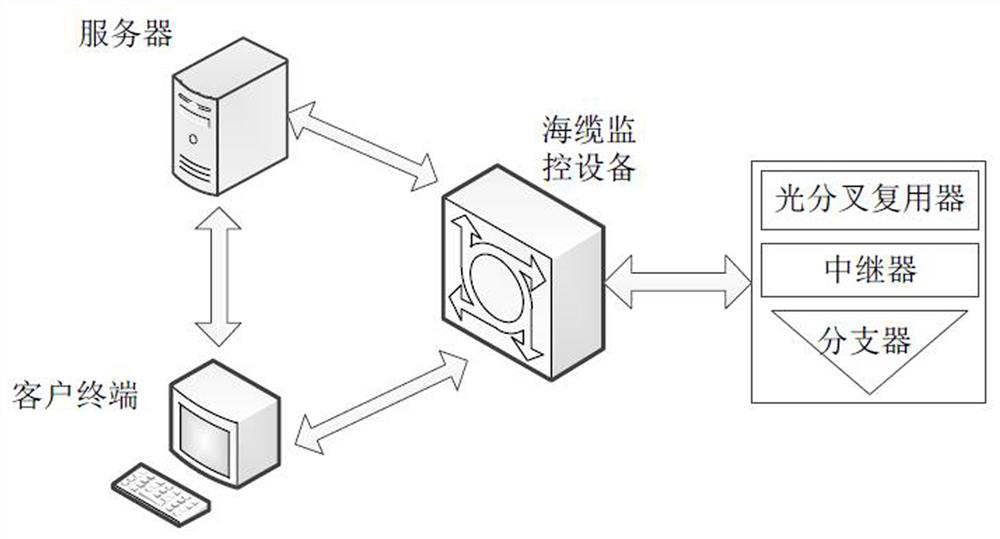
technical field [0001] The present application relates to the technical field of submarine cable systems, in particular to an intelligent feedback system with configurable modulation depth. Background technique [0002] The submarine cable system includes two parts: underwater equipment and water equipment. The underwater equipment is buried on the seabed, including repeaters (RPT, Repeater), branchers (BU, Branching Unit), reconfigurable optical fork multiplexers (ROADM, Reconfigurable Optical Add / Drop Multiplexer), connecting cables; water equipment, located on land, including power supply equipment, network management system (NMS, Network Management System), submarine line termination equipment (SLTE, SubmarineLine Terminating Equipment), submarine cable monitoring equipment (SLM, Submarine Line Management). [0003] The early submarine cable system only had the Command function, that is, the terminal station equipment was used to issue operating instructions to underwat...

Claims


Application Information

Patent Timeline
Patent Type & Authority Patents(China)
IPC IPC(8): H04B10/516H04J14/02
CPCH04B10/516H04J14/021
Inventor 王菲杨礼赵茂
Owner 华海通信技术有限公司
Why Eureka
Try Eureka