
Air heat exchanger and method for producing same and electronic structure equipped therewith

A technology of air heat exchanger and heat exchange plate, applied in the direction of heat exchange equipment, indirect heat exchanger, heat exchanger type, etc.

Pending Publication Date: 2022-03-25
DAU GMBH & CO KG
View PDF1 Cites 0 Cited by
  • Summary
  • Abstract
  • Description
  • Claims
  • Application Information

AI Technical Summary

Problems solved by technology

Although the aim of EP0051315A2 was already to improve the heat dissipation of the individual components, this has not been adequately addressed in EP0051315A2 for components with high thermal power, such as for example power electronics components

Method used


Image

  • Air heat exchanger and method for producing same and electronic structure equipped therewith
  • Air heat exchanger and method for producing same and electronic structure equipped therewith
  • Air heat exchanger and method for producing same and electronic structure equipped therewith

Examples


Embodiment Construction

[0079] At the outset, it should be pointed out that the same parts are provided with the same reference signs or the same component designations in the differently described embodiments, and that the disclosure content contained in the entire description can be transferred to the same parts with the same reference signs or the same component names. . Furthermore, the positional specifications selected in the description, such as eg top, bottom, side, etc., refer to the directly described and shown figures and can be transferred to the new position in the event of a change of position.

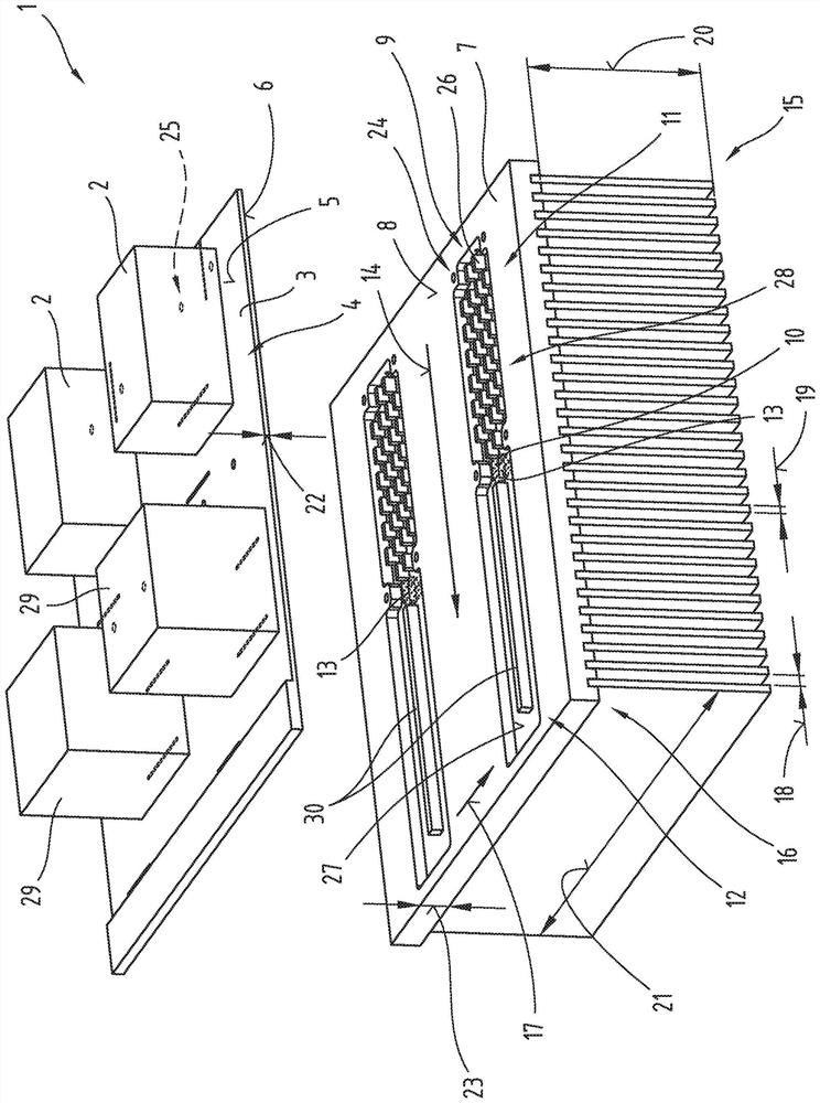
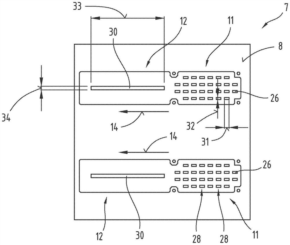
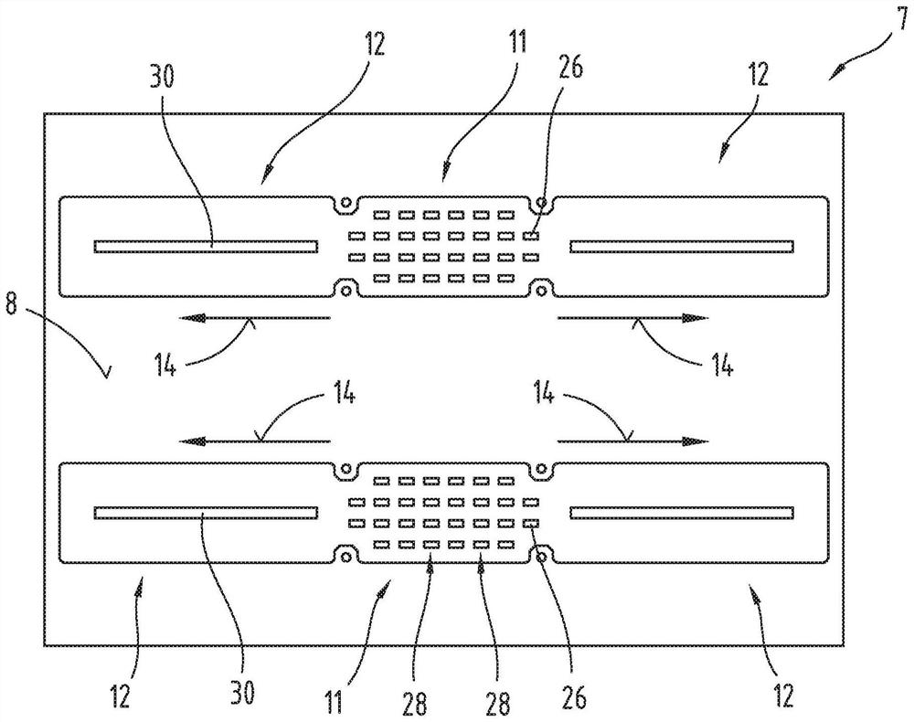
[0080] figure 1 A perspective view of a first exemplary embodiment of an air heat exchanger 1 for cooling power electronics components 2 is shown. Such a power electronic component 2 to be cooled can be, for example, a bipolar transistor with an insulated gate electrode. The air heat exchanger 1 includes a carrier plate 3 which includes a receiving area 4 for receiving power electronics compo...


PUM

PropertyMeasurementUnit
Thicknessaaaaaaaaaa
Thicknessaaaaaaaaaa

Abstract

The invention relates to an air heat exchanger (1) for cooling power electronic components (2), comprising:-a carrier plate (3) having a receiving region (4) for receiving the power electronic components (2); -a heat exchange plate (7) which is coupled to the carrier plate (3), at least one hermetically closed cavity (10) for accommodating a working medium (13) being defined by the carrier plate (3) and the heat exchange plate (7), the cavity (10) having an evaporator (11) and a condenser (12), the evaporator (11) being arranged at a distance from the condenser (12) in the heat transfer direction (14); and a cooling rib (15) coupled to the heat exchange plate (7).

Description

technical field [0001] The invention relates to an air heat exchanger for cooling power electronic components. Background technique [0002] An embodiment of an air heat exchanger is known from EP 0051315 A2. Although the aim of EP0051315A2 was already to improve the heat dissipation of the individual components, this has not yet been adequately addressed in EP0051315A2 for components with high thermal output, such as for example power electronics components. Contents of the invention [0003] The object of the present invention is to overcome the disadvantages of the prior art and to provide an air heat exchanger which also has improved heat dissipation for electronic components with high thermal output. [0004] One possibility to improve heat dissipation consists in the application of liquid heat exchangers. However, liquid heat exchangers have the disadvantage of high energy consumption for cooling medium circulation. Furthermore, liquid heat exchangers have a compl...

Claims


Application Information

Patent Timeline
IPC IPC(8): F28D9/00F28F9/10F28F9/18F28F9/26F28F21/08
CPCF28D15/02F28D15/0266H01L23/46H05K7/20127H05K7/202H05K7/2029H05K7/20336H05K7/20418F28D9/00F28F21/084F28F9/18F28F9/26F28F9/10H01L23/34F28D15/0233F28D15/0275F28F3/048F28F3/022F28D15/04F28F2225/00F28F2240/00H01L23/3672H05K7/20936H05K7/20309H05K7/20318H05K7/20436H05K7/20909
Inventor D·库斯蒂科
Owner DAU GMBH & CO KG
Learn More