Rapid warning and dredging device for tunnel drainage

A tunnel drainage and fast technology, which is applied in the direction of water supply equipment, drainage, mining equipment, etc., can solve the problems of inconvenience, easy blockage and dredging of tunnel drainage pipes, and achieve the effect of solving easy blockage, compact overall structure design, and convenient dredging operations

Active Publication Date: 2022-05-03
山西省水利建筑工程局集团有限公司
View PDF15 Cites 0 Cited by
  • Summary
  • Abstract
  • Description
  • Claims
  • Application Information

AI Technical Summary

Problems solved by technology

[0004] The purpose of the present invention is to solve the shortcomings of the tunnel drainage pipes in the prior art that are easy to block and inconvenient to dredge, and propose a fast warning dredging device for tunnel drainage
[0005] In order to solve the problems of easy blockage and inconvenient dredging of tunnel drainage pipes existing in the prior art, the present invention adopts the following technical solutions:

Method used


Image

  • Rapid warning and dredging device for tunnel drainage
  • Rapid warning and dredging device for tunnel drainage
  • Rapid warning and dredging device for tunnel drainage

Examples


Embodiment 1

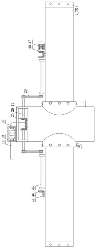
[0029] Embodiment 1: In order to achieve the purpose of facilitating the dredging of tunnel drainage pipes, this embodiment provides a quick warning and dredging device for tunnel drainage, see Figure 1-5 Specifically, it includes a silt discharge cylinder 1 and a drainage pipe 3. The silt discharge cylinder 1 is a hollow cylinder placed vertically. Both sides of the bottom surface of the U-shaped horizontal plate 11 are affixed to both sides of the top surface of the silt discharge cylinder 1, and the middle part of the top wall of the silt discharge cylinder 1 is provided with a bearing ring that penetrates and is fixed. Connected hollow shaft 12, the bottom side of the hollow shaft 12 is provided with a first connecting plate 2, the outer end of the first connecting plate 2 is provided with a first planetary screw mechanism, and the top side of the U-shaped horizontal plate 11 is provided with pumping components;

[0030] Both sides of the central part of the silt dischar...

Embodiment 2

[0040] Embodiment two: in embodiment one, there is also the problem that the inner wall of the silt discharge cylinder is easy to absorb silt and impurities. Therefore, on the basis of embodiment one, this embodiment also includes:

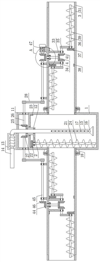
[0041] In the specific implementation process, such as figure 2 and Figure 5 As shown, the first planetary screw mechanism includes a first planetary shaft 21, a first screw blade 24, a first bearing is provided on the outer end of the first connecting plate 2, and a first vertically penetrating first bearing is inserted inside the first bearing. The planetary shaft 21 is located above the first connecting plate 2. The top end of the first planetary shaft 21 is sleeved with a concentric fixed first planetary gear 22. It is located at the concentric position of the first planetary gear 22. The wall is provided with a concentrically fixed first gear ring 23, and the first planetary gear 22 is meshed with the first gear ring 23, and is located bel...

Embodiment 3

[0042] Embodiment 3: In Embodiment 1, there are also problems of inconvenient silt discharge after the installation of some drainage pipes. Therefore, on the basis of Embodiment 1, this embodiment also includes:

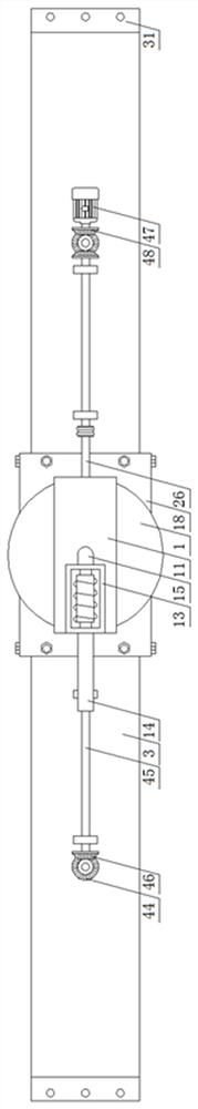
[0043] In the specific implementation process, such as Figure 6 As shown, when several drainage pipes 3 are installed, the joints of two adjacent drainage pipes 3 are all connected to the silt discharge cylinder 1, and the rest of the structure is the same as that in Embodiment 1; A pair of second horizontal shafts 45 are arranged on both sides of the top surface of the corresponding drainage pipe 3 between the cylinders 1, and the opposite ends of the pair of second horizontal shafts 45 are meshed with the sixth bevel gear 44 through the fifth bevel gear 46. , the opposite ends of a pair of second horizontal shafts 45 are connected to the corresponding first horizontal shafts 26 through the driving belt 28. Through the above-mentioned settings, only one servo motor...


PUM


Abstract

The invention discloses a rapid early warning and dredging device for tunnel drainage, which comprises a silt discharge cylinder and a drainage pipe. The outer end is provided with a first planetary screw mechanism, and the top side of the U-shaped horizontal plate is provided with a silt pumping assembly; a pair of drainage pipes are provided on both sides of the middle part of the silt discharge cylinder, and the middle part of the inner top wall of each drainage pipe is provided with a Fixed shaft, a pair of side plates are arranged in the middle of the inner top wall of the drainage pipe, the bottom end of each side plate is equipped with a linkage shaft, and the outer end of each pair of linkage shafts is equipped with a second connecting plate, and each second connecting The outer ends of the plates are provided with a second planetary screw mechanism, and the hollow shaft is connected with a pair of fixed shafts through a linkage mechanism. The invention can collect the silt and impurities together through the wall scraping operation, and then discharge and clean them in time, which facilitates the rapid dredging operation of the drainage pipe and further improves the efficiency of subsequent drainage inside the tunnel.

Description

technical field [0001] The invention relates to the technical field of tunnel drainage, in particular to a rapid early warning dredging device for tunnel drainage. Background technique [0002] Tunnel drainage is an important prerequisite for tunnel construction, normal use and safe operation. The drainage system is directly related to the success or failure of tunnel construction and the function of use. Tunnel drainage pipes refer to pipes pre-buried in concrete to conduct water and drain water. The blockage of tunnel drainage pipes will cause groundwater to be unable to be drained in time, thus posing a major threat to the safety of tunnel structures. [0003] The existing tunnel drainage pipes have the following disadvantages: 1. The silt and impurities in the water are prone to chemical reactions to form crystals and precipitates attached to the inner wall of the pipe to cause blockage. 2. Most of the tunnel drainage pipes are pre-buried in the concrete, and it is inco...

Claims


Application Information

Patent Timeline
Patent Type & Authority Patents(China)
IPC IPC(8): E03F9/00E03F7/00E21F16/02E21F17/18
CPCE03F9/00E03F9/002E03F7/00E21F16/02E21F17/18
Inventor 杨金平杨剑武张瑜郭利军薛晓飞李宝国
Owner 山西省水利建筑工程局集团有限公司
Why Eureka
Try Eureka