Electronic package and fabrication method thereof

A technology for electronic packaging and electronic components, which is applied in the manufacturing of electrical components, electrical solid-state devices, semiconductor/solid-state devices, etc. Inductance value, effect of miniaturization

Pending Publication Date: 2022-03-29
SILICONWARE PRECISION IND CO LTD
View PDF0 Cites 0 Cited by
  • Summary
  • Abstract
  • Description
  • Claims
  • Application Information

AI Technical Summary

Problems solved by technology

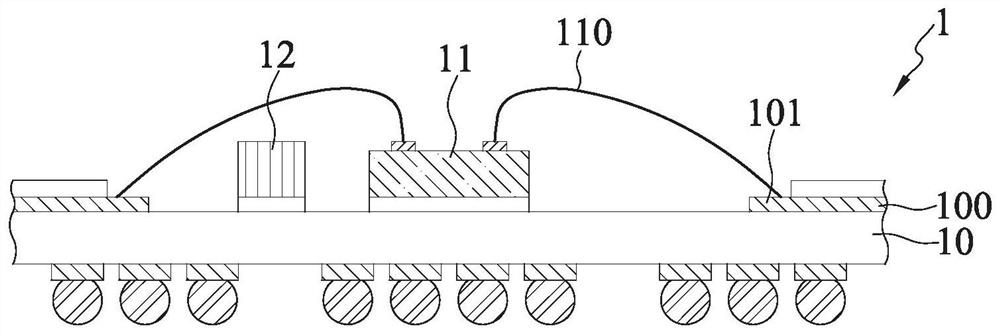
[0006] However, the inductance element 12 is chip type, so it requires a large volume, especially the inductance element 12 required by the power circuit, and the inductance element 12 is too far away from the semiconductor chip 11, causing parasitic effects along with the The inductance element 12 is increased away from the semiconductor chip 11, thus causing the electrical performance of the semiconductor package 1 to be poor.
[0007] In addition, the inductance element 12 is formed on the surface of the packaging substrate 10, which will occupy a large amount of layout space of the packaging substrate 10, thus making it difficult for the semiconductor package 1 to meet the miniaturization requirements.
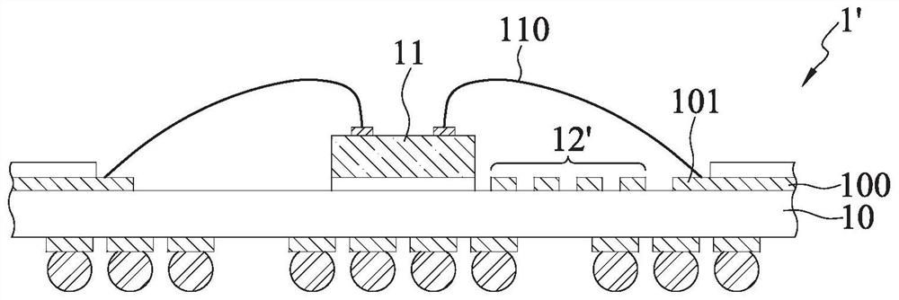
[0008] In addition, the industry also replaces the chip-type inductance element 12 with a coil-type inductance 12', such as figure 1 'shown semiconductor package 1', but the coil-type inductor 12' is only set on the packaging substrate 10, so the analog value of the inductance generated by the coil-type inductor 12' is limited, resulting in the inductance of the coil-type inductor 12' The value is too small to fit the requirement

Method used


Image

  • Electronic package and fabrication method thereof
  • Electronic package and fabrication method thereof
  • Electronic package and fabrication method thereof

Examples


Embodiment Construction

[0072]Embodiments of the present invention are described below through specific examples, and those skilled in the art can easily understand other advantages and effects of the present invention from the content disclosed in this specification.

[0073] It should be noted that the structures, proportions, sizes, etc. shown in the drawings of this specification are only used to match the content disclosed in the specification for the understanding and reading of those skilled in the art, and are not used to limit the conditions for the implementation of the present invention , so it has no technical substantive meaning, and any modification of structure, change of proportional relationship or adjustment of size shall still fall within the scope of the disclosure of the present invention without affecting the functions and objectives of the present invention. The technical content must be within the scope covered. At the same time, terms such as "above", "first", "second" and "o...


PUM


Abstract

The present invention relates to an electronic package and a method of fabricating the same, including disposing at least one magnetic conductive member between a carrier and an electronic component, the electronic component having a first conductive layer, and the carrier having a second conductive layer such that the magnetic conductive member is located between the first conductive layer and the second conductive layer, and a plurality of conductive bumps electrically connected with the first conductive layer and the second conductive layer are arranged between the electronic component and the bearing part so as to surround the magnetic conductive part to generate magnetic flux.

Description

technical field [0001] The present invention relates to a semiconductor device, in particular to an electronic package with a ferromagnetic material and a manufacturing method thereof. Background technique [0002] In general semiconductor application devices, such as communication or high-frequency semiconductor devices, it is often necessary to electrically connect multiple radio frequency (radio frequency) passive components such as resistors, inductors, capacitors, and oscillators to the packaged semiconductor chip. Thus, the semiconductor chip has a specific current characteristic or emits a signal. [0003] Taking a Ball Grid Array (BGA for short) semiconductor device as an example, although multiple passive components are placed on the surface of the substrate, in order to prevent the passive components from hindering the electrical connection and configuration between the semiconductor chip and the multiple pads, Traditionally, the passive elements are mostly placed...

Claims


Application Information

Patent Timeline
Patent Type & Authority Applications(China)
IPC IPC(8): H01L23/64H01L25/16H01L23/31H01L21/50
CPCH01L23/645H01L25/16H01L23/3107H01L21/50H01L28/10H01L23/13H01L23/49822H01L23/49816H01L23/50H01L21/4857H01L23/3128H01L2224/16227H01L2924/15159H01L2924/19042H01L2924/19103H01L2924/19105H01L2224/0401H01L2924/19104H01L23/5227H01L2924/15311H01L2224/04105H01L2224/12105H01L24/20H01L24/16H01L2924/18162H01L2924/30107H01L23/66H01F17/0033H01L23/49838H01L21/4853H01L21/565
Inventor 邱志贤张克维
Owner SILICONWARE PRECISION IND CO LTD
Why Eureka
Try Eureka