Supercharge Your Innovation With Domain-Expert AI Agents!

Welding device of automobile brake

A welding device and brake technology, which is applied in welding equipment, manufacturing tools, resistance welding equipment, etc., can solve problems such as low efficiency, difficult assembly, harmful to health, etc., and achieve the effect of improving efficiency and accelerating cooling speed

Active Publication Date: 2022-04-01
姚阳娟
View PDF9 Cites 0 Cited by
  • Summary
  • Abstract
  • Description
  • Claims
  • Application Information

AI Technical Summary

Problems solved by technology

At present, automobile brakes are divided into disc brakes and drum brakes. For drum brakes, the main structure includes a brake base plate, and part of the brake base plate is provided with shaft holes for installing camshafts. In order to improve the shaft hole The wear resistance of the shaft hole is often welded with a support bushing in the shaft hole. In the traditional process, the welding wire is melted between the support bushing and the shaft hole by means of flame welding to realize the connection and fixation of the two, which takes a long time. Low efficiency, and produce more polluting gas, harmful to health
For this reason, we have adopted the resistance welding method with high welding efficiency, low difficulty and less pollution for the welding of the supporting bushing. The annular groove of the ring, by manually setting the welding ring in the annular groove, and then pressing the support bushing in the shaft hole, and melting the welding ring after power on to realize the connection between the two, but because the welding ring is sleeved During the process, there will be friction with the support bushing, which will make the assembly difficult and lead to low efficiency

Method used


Image

  • Welding device of automobile brake
  • Welding device of automobile brake
  • Welding device of automobile brake

Examples


Embodiment Construction

[0030] In order to make the technical means, creative features, goals and effects achieved by the present invention easy to understand, the present invention will be further described below in conjunction with specific embodiments.

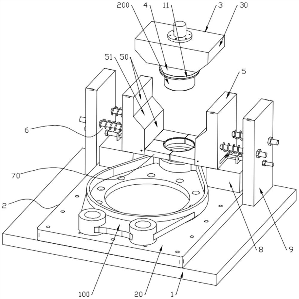
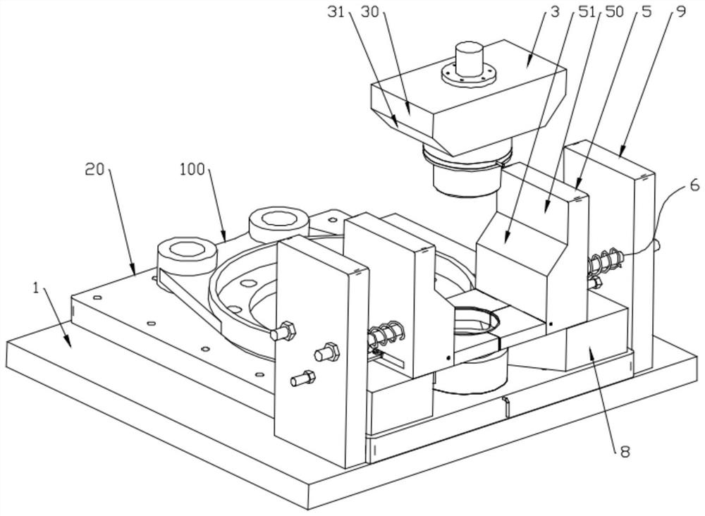
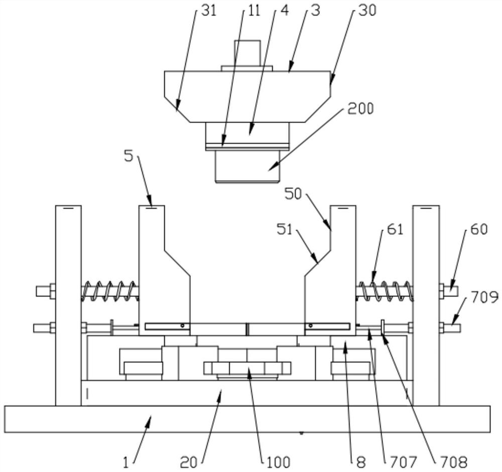
[0031] Such as Figure 1 to Figure 13 As shown, a welding device for an automobile brake includes a base plate 1, a positioning tool 2, a pressure block 3, a hydraulic expansion shaft 4, a guide block 5 and a supporting mechanism 7, and the positioning tool 2 is installed on the base plate 1 and used for Positioning the brake base plate 100, the positioning tool 2 includes a base plate 20 and two positioning pins 21, the base plate 20 is installed on the base plate, and the positioning pins 21 are fixed on the base plate 20 and connected with the mounting holes on the brake base plate 100 Matching, the positive conductive plate 10 is embedded in the positioning tool 2 below the shaft hole on the brake base plate 100;

[0032] The lower end of the...


PUM


Abstract

The invention discloses a welding device for an automobile brake, and relates to the field of welding equipment, the welding device comprises a bottom plate, a positioning tool, a pressing block, a hydraulic expansion shaft, a guide block and a bearing mechanism, semi-automatic or automatic assembly of a welding ring and a supporting shaft sleeve is achieved by means of the guide block and the bearing mechanism, and the welding ring and the supporting shaft sleeve are assembled in cooperation with a positive conducting plate and a negative conducting ring. And compared with traditional manual assembly, the supporting shaft sleeve and the shaft hole are welded and fixed, and the efficiency is remarkably improved.

Description

technical field [0001] The invention belongs to the field of welding equipment, and in particular relates to a welding device for automobile brakes. Background technique [0002] As a braking component, the brake is widely used in the automotive field. At present, automobile brakes are divided into disc brakes and drum brakes. For drum brakes, the main structure includes a brake base plate, and some brake base plates are provided with shaft holes for installing camshafts. In order to improve the shaft hole The wear resistance of the shaft hole is often welded with a support sleeve in the shaft hole. In the traditional process, the welding wire is melted between the support sleeve and the shaft hole by means of flame welding to realize the connection and fixation of the two, which takes a long time. The efficiency is low, and more polluting gases are produced, which is harmful to health. To this end, we have adopted a resistance welding method with high welding efficiency, ...

Claims


Application Information

Patent Timeline
IPC IPC(8): B23K11/36
CPCY02P70/10
Inventor 姚阳娟
Owner 姚阳娟
Features
  • R&D
  • Intellectual Property
  • Life Sciences
  • Materials
  • Tech Scout
  • Unparalleled Data Quality
  • Higher Quality Content
  • 60% Fewer Hallucinations
Learn More