
Bridge demolition construction method and equipment thereof

A technology for construction equipment and bridges, applied in building maintenance, construction, building construction, etc., can solve the problems of declining resistance of functional bridge structures, high construction risks for workers, and increased demolition needs, so as to improve safety and convenience. The effect of solving the difficulty of drilling blasting holes and improving the construction efficiency

Pending Publication Date: 2022-04-01
CHONGQING VOCATIONAL COLLEGE OF TRANSPORTATION
View PDF0 Cites 0 Cited by
  • Summary
  • Abstract
  • Description
  • Claims
  • Application Information

AI Technical Summary

Problems solved by technology

[0002] With the accelerated development of my country's basic transportation facilities, due to factors such as congenital design and construction quality defects, changes in use functions, road network re-planning, environmental erosion and vehicle overloading during operation, the structural resistance of bridges has rapidly declined, and the safety of many bridges , reliability and traffic capacity are difficult to meet the growing traffic demand, and the demand for demolition is increasing
[0003] Bridge demolition is a special bridge construction work with great technical difficulty and high safety risks. At present, the domestic construction techniques and methods in the direction of bridge demolition are not systematic and perfect.
For the demolition of water surface bridges, after the bridge deck of the water surface bridge is removed, the bottom of the remaining pier is underwater, especially for a single cylindrical pier, there is no stable ground around it for support, so it is necessary to blast the pier During demolition, the drilling rig cannot stably drill blast holes that meet the blasting requirements on the side wall of the pier, which makes the blasting demolition of underwater pier more difficult, and the construction risks for workers are high

Method used


Image

  • Bridge demolition construction method and equipment thereof
  • Bridge demolition construction method and equipment thereof
  • Bridge demolition construction method and equipment thereof

Examples


Embodiment Construction

[0048] The specific implementation manner of the present invention will be described in more detail below with reference to schematic diagrams. The advantages and features of the present invention will be more apparent from the following description. It should be noted that all the drawings are in a very simplified form and use imprecise scales, and are only used to facilitate and clearly assist the purpose of illustrating the embodiments of the present invention.

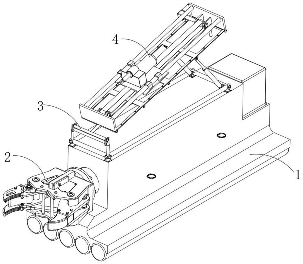
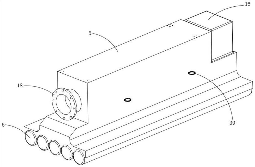
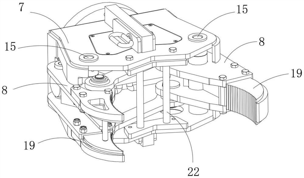
[0049] Such as Figure 1-Figure 8 As shown, the bridge demolition construction equipment provided by the embodiment of the present invention is used to stably drill blast holes meeting the blasting requirements on the side wall of the bridge pier on the water surface, so as to facilitate the blasting demolition of the bridge pier. The equipment comprises a floating mechanism 1, a clamping mechanism 2 arranged at one end of the floating mechanism 1, an inclination adjustment mechanism 3 arranged at the top of the f...


PUM


Abstract

The invention provides a bridge demolition construction method and equipment thereof. The equipment comprises a floating mechanism, a clamping mechanism arranged at one end of the floating mechanism, an inclination angle adjusting mechanism arranged at the top of the floating mechanism and a drilling mechanism installed on the inclination angle adjusting mechanism. According to the bridge demolition construction equipment, drilling operation can be stably conducted on the side wall of a water surface pier on the water surface, and after drilling is conducted, blasting personnel can conduct blasting demolition on the pier after charging explosives into a hole. The bridge demolition construction equipment is high in reliability and automation degree, the problem that blast holes are difficult to drill when water surface piers are demolited at present is effectively solved, the construction safety and convenience of workers are improved, and the construction efficiency of the workers is effectively improved.

Description

technical field [0001] The invention relates to the technical field of bridge construction, in particular to a bridge demolition construction method and equipment thereof. Background technique [0002] With the accelerated development of my country's basic transportation facilities, due to factors such as congenital design and construction quality defects, changes in use functions, road network re-planning, environmental erosion and vehicle overloading during operation, the structural resistance of bridges has rapidly declined, and the safety of many bridges , reliability and traffic capacity are difficult to meet the growing traffic demand, and the demand for demolition is increasing. [0003] Bridge demolition is a special bridge construction work with great technical difficulty and high safety risks. At present, the construction techniques and methods in the direction of bridge demolition in China are not systematic and perfect enough. For the demolition of water surface ...

Claims


Application Information

Patent Timeline
IPC IPC(8): E01D24/00
Inventor 王秋云梁静
Owner CHONGQING VOCATIONAL COLLEGE OF TRANSPORTATION
Learn More