In-situ detection device and in-situ detection method for edge cutting wafer

A detection device and wafer technology, applied in the semiconductor field, can solve the problems of affecting the normal interaction of wafers, easily causing false alarms, and low switching efficiency, so as to reduce the probability of false alarms in in-situ detection, ensure smoothness, and enhance applicability sexual effect

Pending Publication Date: 2022-04-01
HWATSING TECH
View PDF0 Cites 0 Cited by
  • Summary
  • Abstract
  • Description
  • Claims
  • Application Information

AI Technical Summary

Problems solved by technology

[0005] (2) In order to prevent the device area from being polluted by light, the optical sensor cannot be used for detection;
However, for edge-cut wafers, it is difficult for the wafer to completely cover or mostly cover the water outlet, resulting in a small pressure difference when there is a wafer or not, which can easily cause false alarms and affect the normal interaction of the wafer;
[0007] (4) Since there are many specifications of wafer edge cutting size (trimming size), and the overall replacement of mechanical parts to match wafers of different specifications has the disadvantages of low switching efficiency and high overall cost

Method used


Image

  • In-situ detection device and in-situ detection method for edge cutting wafer
  • In-situ detection device and in-situ detection method for edge cutting wafer
  • In-situ detection device and in-situ detection method for edge cutting wafer

Examples


Embodiment Construction

[0043] The technical solutions of the present invention will be described in detail below in conjunction with specific embodiments and accompanying drawings. The examples described here are specific implementations of the present invention and are used to illustrate the concept of the present invention; these descriptions are all explanatory and exemplary, and should not be construed as limiting the implementation of the present invention and the protection scope of the present invention . In addition to the embodiments described here, those skilled in the art can also adopt other obvious technical solutions based on the claims of the application and the contents disclosed in the specification, and these technical solutions include adopting any modifications made to the embodiments described here. Obvious alternatives and modified technical solutions.

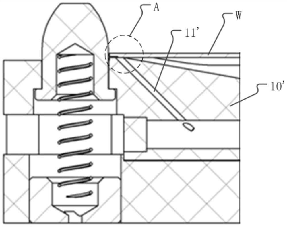
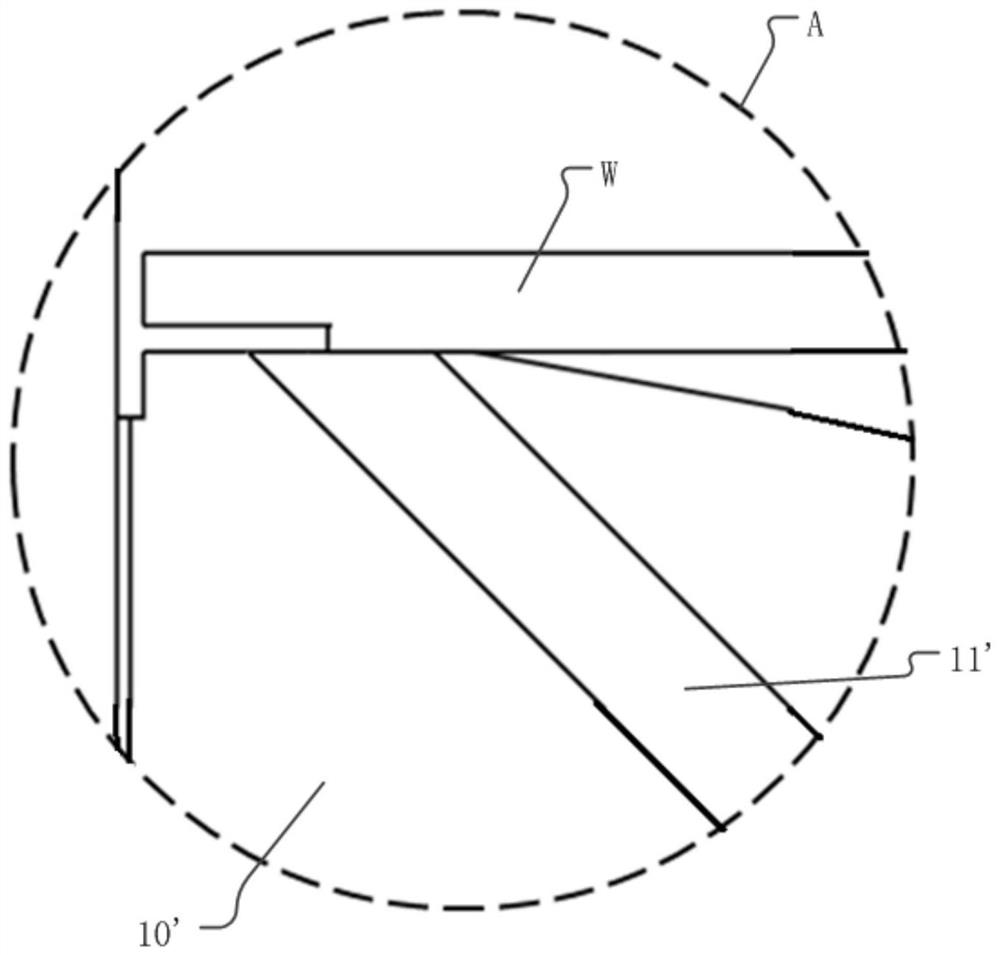
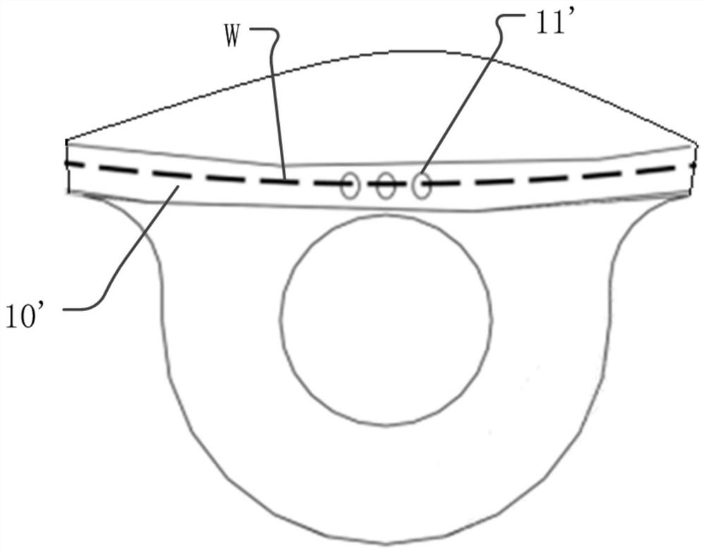
[0044] The accompanying drawings in this specification are schematic diagrams, which assist in explaining the concept of the...


PUM


Abstract

The invention discloses an in-situ detection device and an in-situ detection method for an edge cutting wafer, and the device comprises an inclined hole which is disposed at the top of a bracket; the medium source is communicated with the inclined hole through a pipeline; the pressure sensor is arranged on the pipeline between the inclined hole and the medium source so as to detect the pressure of the pipeline; the control part is connected with the pressure sensor so as to judge whether the wafer is in place or not according to the pressure of the pipeline; wherein the top of the bracket is further provided with a groove overlapped with the inclined hole, a base plate is installed in the groove, and the base plate partially shields the inclined hole to form a detection hole; and if the wafer on the bracket is in place, the wafer partially or completely blocks the detection hole to cause the pressure change of the pipeline.

Description

technical field [0001] The invention belongs to the technical field of semiconductors, and in particular relates to an in-position detection device and an in-position detection method for edge-cut wafers. Background technique [0002] In the field of semiconductors, it is necessary to perform wafer edge trimming on the edge of the wafer, so that a ring-shaped area with a thinner thickness appears on the edge of the wafer, so as to meet the requirements of wafer manufacturing. [0003] In the chemical mechanical polishing process, the on-site detection of the edge-cut wafer is prone to misjudgment, which affects the normal interaction of the wafer in the wafer exchange device (load cup). specifically: [0004] (1) Due to the requirements of the wafer device area, the accessible area of ​​the wafer is limited to within 2.5mm of the edge; the 2.5mm edge area is not only used for the support of the wafer, but also for the in-position detection of the wafer, utilizing the space ...

Claims


Application Information

Patent Timeline
Patent Type & Authority Applications(China)
IPC IPC(8): H01L21/66
Inventor 吴兴许振杰陈映松
Owner HWATSING TECH
Why Eureka
Try Eureka