
Circularly polarized spaceborne antenna based on 3dB bridge and spaceborne phased array

A spaceborne antenna, circular polarization technology, applied in the field of antennas, can solve the problems of the beam width of the transmission signal and the axial ratio bandwidth meeting the requirements, and achieve the effect of improving the normal gain and reducing the radiation leakage.

Pending Publication Date: 2022-04-01
重庆两江卫星移动通信有限公司
View PDF0 Cites 0 Cited by
  • Summary
  • Abstract
  • Description
  • Claims
  • Application Information

AI Technical Summary

Problems solved by technology

[0005] The technical problem to be solved by the present invention is that in the antenna of the prior art, when the microstrip antenna meets the low-profile characteristics, the transmission signal beam width and the axial ratio bandwidth cannot meet the requirements, and the purpose is to provide a 3dB bridge-based Circularly polarized space-borne antennas and space-borne phased arrays can enable microstrip antennas to achieve wide beams, wide-axis ratio bandwidths, and low-profile characteristics within the operating frequency band

Method used


Image

  • Circularly polarized spaceborne antenna based on 3dB bridge and spaceborne phased array
  • Circularly polarized spaceborne antenna based on 3dB bridge and spaceborne phased array
  • Circularly polarized spaceborne antenna based on 3dB bridge and spaceborne phased array

Examples


Embodiment 1

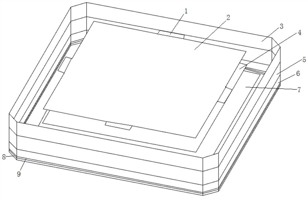
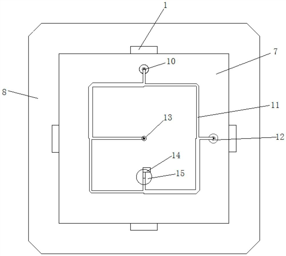
[0034] This embodiment discloses a circularly polarized spaceborne antenna based on a 3dB bridge, such as Figure 1~3 As shown, it includes a feed layer and a dielectric layer. A first metal patch 7 is arranged between the feed layer and the dielectric layer. The first metal patch 7 is located in the center of the entire antenna and is a square patch. sheet; the feed layer is provided with a 3dB coupling bridge 11, in the present embodiment, the 3dB coupling bridge 11 used is a 3dB coupling flyover in stripline form, and the output end of the 3dB coupling bridge 11 is connected to the first A metal patch 7 is connected to circularly polarize the input signal, and transmit the circularly polarized signal to the dielectric layer; the dielectric layer is used to widen the bit width of the circularly polarized signal, and The circularly polarized signal radiates outward.

[0035] In the feed layer, it includes the third dielectric plate 6 and the fourth dielectric plate 9, as wel...

Embodiment 2

[0050] This embodiment discloses a circularly polarized space-borne phased array based on a 3dB bridge. The space-borne antenna unit used in this embodiment to form the space-borne phased array is the circularly polarized space-borne antenna disclosed in Embodiment 1, and The plurality of circularly polarized space-borne antennas are evenly arranged in the form of an array, which can improve the performance of the phased array.


PUM


Abstract

The invention discloses a circularly polarized spaceborne antenna based on a 3dB bridge and a spaceborne phased array. A first metal patch is arranged between a feed layer and a dielectric layer; the feed layer is provided with a 3dB coupling bridge, the output end of the 3dB coupling bridge is connected with the first metal patch, and the 3dB coupling bridge is used for circularly polarizing an input signal and transmitting the circularly polarized signal to the dielectric layer; the dielectric layer is used for widening the bit width of the circularly polarized signal and radiating the widened circularly polarized signal outwards; the beneficial effects of the invention are that in the required working frequency band, the axial ratio is lower than 3dB, the standing wave is lower than 1.5, the beam width at the working frequency point is greater than 90 degrees, and the low profile is satisfied; circular polarization is realized in a forced feed mode, and the double-feed mode enables the circular polarization bandwidth to be broadened greatly compared with a common single-feed mode. The radiation leakage of the back surface is reduced, and the normal gain of the antenna and the gain during large scanning angle scanning are improved.

Description

technical field [0001] The invention relates to the technical field of antennas, in particular to a circularly polarized space-borne antenna and a space-borne phased array based on a 3dB electric bridge. Background technique [0002] In recent years, in the field of satellite communication, in order to achieve effective coverage of specific areas of the earth, the EIRP (Effective Isotropic Radiated Power) of the phased array is improved to achieve less interference from adjacent cells, and the satellite-borne phase The unit antenna design of the control array antenna puts forward strict requirements, and there are great limitations in terms of antenna size, bandwidth, and axial ratio. [0003] In a satellite communication system, the type of antenna is limited. The commonly used microstrip antenna can easily meet the low-profile characteristics, but the signal transmitted by the antenna cannot meet the requirements of beam width and axial ratio bandwidth. Therefore, the used...

Claims


Application Information

Patent Timeline
IPC IPC(8): H01Q1/38H01Q1/50H01Q15/24H01Q21/06
Inventor 谭秋意刘又嘉黄海燕鲁国林
Owner 重庆两江卫星移动通信有限公司
Learn More