Vacuum tank cover, vacuum pouring device with vacuum tank cover and pouring method

A technology of vacuum tank cover and vacuum pouring, which is applied in the direction of manufacturing tools, casting melt containers, metal processing equipment, etc. The effect of reducing the pre-vacuum time

Pending Publication Date: 2022-04-05
ZHANGJIAGANG CITY GUANGDA MACHINERY FORGING
View PDF5 Cites 0 Cited by
  • Summary
  • Abstract
  • Description
  • Claims
  • Application Information

AI Technical Summary

Problems solved by technology

[0006] The purpose of this application is to provide a vacuum tank cover, in which a sealing structure is arranged at the gate position, so as to solve the problems of the pre-pumping time and the argon blowing time of the slide plate in the prior art before the vacuum steel ingot pouring is too long

Method used


Image

  • Vacuum tank cover, vacuum pouring device with vacuum tank cover and pouring method
  • Vacuum tank cover, vacuum pouring device with vacuum tank cover and pouring method
  • Vacuum tank cover, vacuum pouring device with vacuum tank cover and pouring method

Examples


Embodiment 1

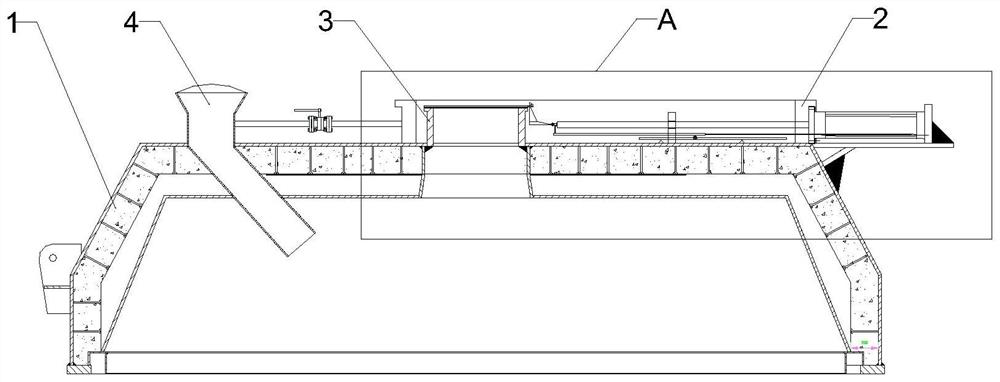
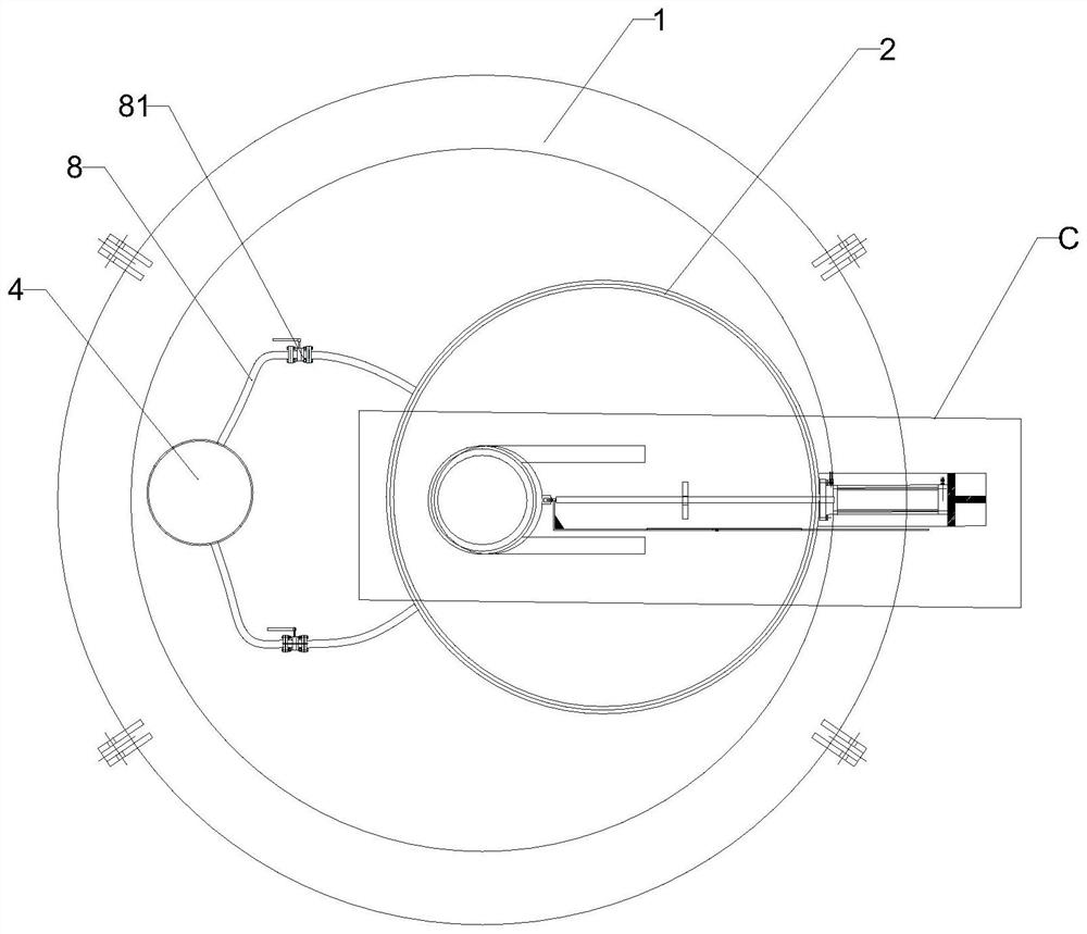
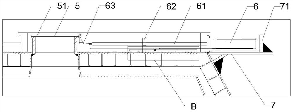
[0047] figure 1 It is a structural schematic diagram of a vacuum tank cover in this embodiment, figure 2 for figure 1 top view of image 3 for figure 1 Partial enlarged view of A in the figure. like Figure 1-3 As shown, a sealing ring 2 for installing a refining bag is arranged on the top of the vacuum tank cover 1 described in this embodiment, and a pouring port 3 is arranged in the sealing ring 2, and the position of the pouring port 3 corresponds to the position of the refining bag water port, Used to receive molten steel from refining. A sealing cover plate 5 is arranged on the pouring port 3 , the shape and size of the sealing cover plate 5 are adapted to the pouring port 3 , and the pouring port 3 can be completely covered and sealed. The side of the sealing cover 5 is provided with a cylinder 6, and the telescopic rod 61 of the cylinder 6 is connected with the side of the sealing cover 5, and the telescopic movement of the telescopic rod can drive the sealing cove...

Embodiment 2

[0055] The difference between this embodiment and Embodiment 1 is that a cylinder scale 9 is provided on one side of the cylinder 6 to display the telescopic position of the telescopic rod 61 and then determine the position of the sealing cover 5 . specifically, Figure 7 for image 3 Partial enlargement of B in the figure, combined with Figure 6-7 , The cylinder scale 9 is specifically a long rod, which is arranged on one side of the cylinder 6 and passes through the side wall of the sealing ring 2 . One end of the cylinder scale 9 is exposed outside the sealing ring 2, and the other end is connected with the end of the telescopic rod 61. When the telescopic rod 61 stretches, it drives the cylinder scale 9 to move. And when the refining bag is installed on the seal ring 2, the situation in the seal ring 2 is covered, and the position of the telescopic rod 61 and the sealing cover plate 5 can be determined by the cylinder scale exposed outside.

[0056] Specifically, below...

Embodiment 3

[0058] The difference between this embodiment and Embodiment 1 is that a charging bell 4 is also provided on the vacuum tank cover 1, and the charging bell 4 is used for connecting a quick connector.


PUM


Abstract

The invention discloses a vacuum tank cover, a vacuum pouring system with the vacuum tank cover and a pouring method, and relates to the technical field of pouring. According to the vacuum tank, the sealing cover plate is arranged on the sprue gate, so that the sealing performance of the vacuum tank is improved, the pre-vacuumizing time before pouring can be greatly shortened, and the vacuum degree in the vacuum tank can be kept after pre-vacuumizing. During use, after a sealing ring is arranged in a refining package, the pressure above and below the sealing cover plate is balanced through the balance pipe, and then the sealing cover plate is dragged away from the sprue gate through the air cylinder, so that pouring is realized, and the sliding plate argon blowing time before pouring is shortened.

Description

technical field [0001] The present application relates to the technical field of vacuum steel ingot pouring, in particular to a vacuum tank cover, a vacuum pouring device and a pouring method thereof. Background technique [0002] At present, most of the VC vacuum casting equipment has a tundish as a transition. A tundish has the advantages of being able to cast multiple packages together and produce larger steel ingots, which can produce more than 600 tons of steel ingots. However, due to problems such as secondary oxidation, slag due to the inability to close the stopper, and corrosion of the refractory material of the tundish when pouring with a tundish, foreign inclusions were introduced during the pouring process, resulting in the failure of the nondestructive testing of the forging. For small-tonnage VC steel ingots, product flaw detection requirements are often higher than those for large-tonnage forgings. While trying to improve the process control capabilities of va...

Claims


Application Information

Patent Timeline
Patent Type & Authority Applications(China)
IPC IPC(8): B22D41/58B22D41/50B22D41/24C21C7/10
Inventor 袁明于广文史以兵顾金才徐文斌王光玮
Owner ZHANGJIAGANG CITY GUANGDA MACHINERY FORGING
Why Eureka
Try Eureka