
Pre-cooling device of superfluid helium system

A technology of pre-cooling and cold head, which is applied in the direction of refrigeration and liquefaction, liquefaction, solidification, etc., and can solve the problem of long pre-cooling time

Active Publication Date: 2022-04-05
TECHNICAL INST OF PHYSICS & CHEMISTRY - CHINESE ACAD OF SCI
View PDF6 Cites 1 Cited by
  • Summary
  • Abstract
  • Description
  • Claims
  • Application Information

AI Technical Summary

Problems solved by technology

[0005] An embodiment of the present invention provides a precooling device for a superfluid helium system, which is used to solve the problem that the precooling time is too long when the superfluid helium system is precooled by a refrigerator in the prior art

Method used


Image

  • Pre-cooling device of superfluid helium system
  • Pre-cooling device of superfluid helium system
  • Pre-cooling device of superfluid helium system

Examples


Embodiment Construction

[0036] Embodiments of the present invention will be further described in detail below in conjunction with the accompanying drawings and examples. The following examples are used to illustrate the present invention, but should not be used to limit the scope of the present invention.

[0037] In the description of the embodiments of the present invention, it should be noted that the terms "center", "longitudinal", "transverse", "upper", "lower", "front", "rear", "left", "right" , "vertical", "horizontal", "top", "bottom", "inner", "outer" and other indicated orientations or positional relationships are based on the orientations or positional relationships shown in the drawings, and are only for the convenience of describing this The embodiments and simplified descriptions of the invention do not indicate or imply that the devices or elements referred to must have a specific orientation, be constructed and operate in a specific orientation, and therefore should not be construed a...


PUM


Abstract

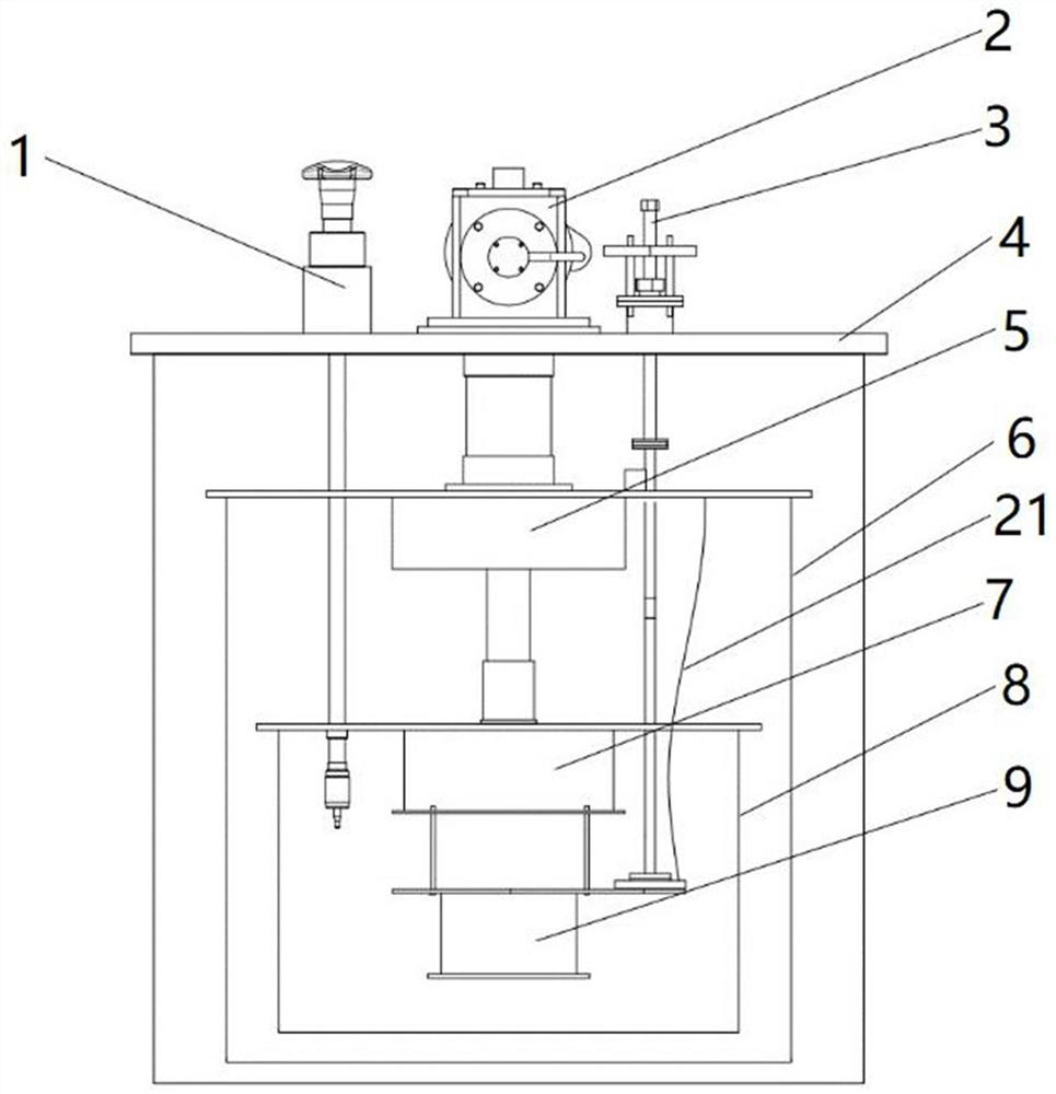
The embodiment of the invention provides a precooling device of a superfluid helium system. The precooling device comprises a vacuum cover, a refrigerating machine, a heat exchanger, a condenser, a superfluid helium cavity, a low-temperature throttling valve and a mechanical thermal switch. The refrigerating machine is provided with a first-stage cold head and a second-stage cold head, and the first-stage cold head and the second-stage cold head are both located in the vacuum cavity of the vacuum cover. The first-stage cold head is connected with the heat exchanger, the second-stage cold head is connected with the condenser, and the low-temperature throttling valve is connected with the condenser and the superfluid helium cavity, so that liquid helium is converted into superfluid helium. The mechanical thermal switch is inserted in the vacuum cover in a lifting mode, one end of the mechanical thermal switch penetrates into an inner cavity of the vacuum cover and extends to the superfluid helium cavity, a heat conduction flange is arranged at the lower end of the mechanical thermal switch, and the heat conduction flange can make contact with or be separated from the superfluid helium cavity. The heat conduction flange is connected with the first-stage cold head through a heat conduction piece so as to transmit the cooling capacity of the first-stage cold head to the heat conduction flange. The precooling device can greatly shorten the precooling time of the superfluid helium system.

Description

technical field [0001] The invention relates to the technical field of cryogenic cooling, in particular to a precooling device for a superfluid helium system. Background technique [0002] Low temperature environment is very important for some large scientific projects. Large-scale scientific projects such as particle cyclotrons and thermonuclear fusion experimental reactors require extremely low temperatures to cool some important internal components in order to achieve the desired effect. In addition, in low temperature environments, some materials will exhibit completely different properties than those at normal temperature. For example, stainless steel will be magnetized, and superconducting materials will achieve superconductivity when they reach their low-temperature transition temperature. At the same time, the properties testing of some special materials at low temperature requires the construction of a corresponding low temperature system. [0003] Directly immer...

Claims


Application Information

Patent Timeline
Patent Type & Authority Applications(China)
IPC IPC(8): F25J1/02
CPCY02E30/10
Inventor 贾朋徐冬王维张恒成黄荣进沈福至王永光李来风
Owner TECHNICAL INST OF PHYSICS & CHEMISTRY - CHINESE ACAD OF SCI
Learn More