
Pre-cooling device before filling of liquid helium storage tank

A liquid helium storage tank technology, which is applied in the field of pre-cooling devices before filling the liquid helium storage tank, can solve the problems of large consumption of liquid helium resources, high time cost, and high price, and achieve lower requirements, reduced consumption, and reduced The effect of pre-cooling time

Active Publication Date: 2021-06-11
SOUTHWEST PETROLEUM UNIV
View PDF25 Cites 0 Cited by
  • Summary
  • Abstract
  • Description
  • Claims
  • Application Information

AI Technical Summary

Problems solved by technology

However, these methods have not penetrated into the liquid helium temperature zone. If they are directly applied to the precooling of liquid helium storage tanks, there will be the following problems: (1) As liquid helium is currently the natural resource with the lowest boiling point, it is difficult to find a low boiling point. The low-temperature working fluid of liquid helium directly precools the storage tank to the liquid helium temperature zone; (2) if the storage tank is directly pre-cooled by using liquid helium as the cold source, it will face the problems of large consumption of liquid helium resources and high price. Even if the method of circulating precooling is adopted, it is restricted by the capacity of the helium liquefaction device of the natural gas helium extraction plant, and the time cost is huge; (3) if the method of precooling liquid helium and other cryogenic working fluids is used, considering the quality of the liquid helium product The purity requirement is extremely high. How to ensure that the residual amount of other low-temperature working fluids in the storage tank will not affect the quality of the externally infused liquid helium product is a problem that must be faced by this method.

Method used


Image

  • Pre-cooling device before filling of liquid helium storage tank

Examples


Embodiment Construction

[0023] The present invention will now be described in further detail with reference to the accompanying drawings. These drawings are all simplified schematic diagrams, and only illustrate the basic structure of the present invention in a schematic manner, so they only show the structures related to the present invention.

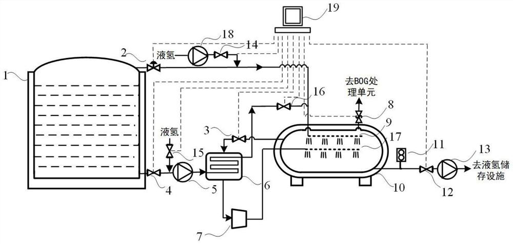
[0024] A liquid helium storage tank pre-cooling device before filling, including 1 liquid helium storage tank, 2 throttle valves, 3 return injection shut-off valves, 4 liquid helium shut-off valves, 5 liquid helium cryopumps, 6 heat exchangers, 7 compressors machine, 8 safety valves, 9 injection devices, 10 liquid helium storage tanks, 11 density meters, 12 first liquid hydrogen shut-off valves, 13 first liquid hydrogen cryopumps, 14 second liquid hydrogen shut-off valves, 15 third liquid hydrogen shut-off valves Valve, 16 one-way valve, 17 second injection device, 18 second liquid hydrogen cryopump, 19 control unit.

[0025] More specifically, before the p...


PUM


Abstract

The invention discloses a pre-cooling device before filling of a liquid helium storage tank, and relates to the technical field of pre-cooling of liquid helium storage tanks. The pre-cooling device comprises the liquid helium storage container, a throttle valve, a low-temperature pump, a heat exchanger, a compressor, a safety valve, an injection device, a liquid helium storage tank, a densitometer, a one-way valve, a second injection device, a control unit, various stop valves and the like. A method of liquid hydrogen preliminary pre-cooling, helium soaking pre-cooling and liquid helium evaporation pre-cooling is adopted, compared with other pre-cooling devices, cold energy of helium in the liquid helium storage container is fully utilized, the liquid helium consumption is reduced, and the process economic benefits are improved. A helium soaking pre-cooling method is adopted, the liquid helium storage tank is further cooled, residual hydrogen is liquefied and discharged, it is guaranteed that the purity of a product is qualified, meanwhile, a liquid helium evaporation pre-cooling method is adopted, the heat exchange rate of helium and the liquid helium storage tank is increased, and the pre-cooling time is shortened.

Description

technical field [0001] The invention relates to the technical field of pre-cooling of liquid helium storage tanks, in particular to a pre-cooling device for liquid helium storage tanks before filling. Background technique [0002] Helium has a very low boiling point (4.2K), critical temperature (5.15K) and critical pressure (0.226MPa), which can easily achieve ultra-low temperature cooling that cannot be achieved by other low-temperature liquids, so it is used in aerospace, nuclear weapons, submarines, and saturation diving operations. , nuclear magnetic resonance, semiconductor and other scientific and technological fields have played an irreplaceable role. At present, my country's annual helium demand exceeds 2.2 × 10 7 m 3 , but my country only has one in Sichuan with an annual output of 6 × 10 4 m 3 The helium extraction plant in Hetianhe Gas Field and Ake Gas Field is still under construction. Almost all helium supply depends on imports, and the international helium...

Claims


Application Information

Patent Timeline
Patent Type & Authority Applications(China)
IPC IPC(8): F25J1/00F25J1/02
CPCF25J1/0007F25J1/0257Y02E60/32
Inventor 贾文龙蒲兼林李长俊吴瑕张财功王硕
Owner SOUTHWEST PETROLEUM UNIV
Learn More