Quick precooling method of low-temperature medium pipeline system

A low-temperature medium and pipeline system technology, which is applied in the pipeline system, container discharge method, container filling method, etc., can solve the problems of insufficient use of containers, low utilization efficiency of low-temperature medium cooling capacity, and large consumption of low-temperature medium. Achieve the effects of reducing media consumption, shortening pre-cooling time, and improving utilization efficiency

Active Publication Date: 2021-07-16
XIAN AEROSPACE PROPULSION INST
View PDF11 Cites 0 Cited by
  • Summary
  • Abstract
  • Description
  • Claims
  • Application Information

AI Technical Summary

Problems solved by technology

Although pre-cooling is carried out by switching between large and small flow rates, the residual pressure of the container is not fully utilized, the consumption of low-temperature medium is still large during the pre-cooling process, and the pre-cooling time is long
[0005] Chinese patent CN110145684A is a low-temperature storage tank pre-cooling system and pre-cooling method. The pre-cooling method mentioned is natural pre-cooling. The pre-cooling medium passes through No. 1 low-temperature storage tank, No. 2 low-temperature storage tank, and No. 3 low-temperature storage tank in sequence. It seems that the cooling capacity is fully utilized, but there is no flow and pressure control requirements in the pre-cooling process, and the storage tank is cooled by natural convection heat exchange, and the pre-cooling cycle is very long
[0006] Chinese patent CN104482404A pre-cooling process of low-temperature super-large liquefied natural gas storage tank, the liquefied natural gas is sprayed into the storage tank through the spray ring on the top of the storage tank (1C) to realize spray cooling of the tank body, which improves the pre-cooling efficiency to a certain extent, but there is no Flow and pressure control requirements, large pre-cooling consumption, long pre-cooling time
[0007] Although the above existing systems and methods can achieve the purpose of pre-cooling, they all have the following disadvantages: 1) the pre-cooling time is long; 2) the cooling capacity utilization efficiency of the low-temperature medium is low

Method used


Image

  • Quick precooling method of low-temperature medium pipeline system

Examples


Embodiment Construction

[0048] The present invention will be further described below in conjunction with the accompanying drawings and exemplary embodiments.

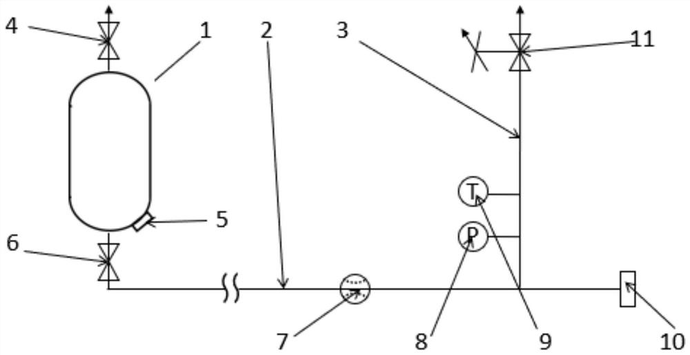
[0049] refer to figure 1 , the present invention provides a rapid precooling method for a low-temperature medium pipeline system, the low-temperature medium pipeline system includes: a low-temperature container 1, a low-temperature pipeline 2 and a pre-cooling discharge pipeline 3; the top of the low-temperature container 1 is provided with The exhaust valve 4 is provided with an injection hole 5 and an output valve 6 at the bottom, and the output valve 6 is connected with the input port of the cryogenic pipeline 2; a mass flow meter 7 is provided on the cryogenic pipeline 2, and a The connection port 10 of the test piece, the low temperature pipeline 2 is connected with the precooling discharge pipeline 3, the precooling discharge pipeline 3 is provided with a pressure sensor 8 and a temperature sensor 9 near the input port, and the output po...


PUM


Abstract

The invention relates to a precooling process of a low-temperature medium pipeline, in particular to a quick precooling method of a low-temperature medium pipeline system. The quick precooling method of the low-temperature medium pipeline system is used for overcoming the defects of long precooling time and lower utilization efficiency of cold energy of a low-temperature medium in the prior art. The quick precooling method of the low-temperature medium pipeline system comprises the following steps of: 1) injecting a low-temperature medium into a low-temperature container; 2) performing early-stage precooling by adopting a high-pressure small-flow mode; 3) performing first-time mode switching; 4) performing middle-stage precooling by adopting a low-pressure large-flow mode; 5) performing second-time mode switching; and 6) performing later-stage precooling by adopting a low-pressure small flow.

Description

technical field [0001] The invention relates to a precooling process for a low-temperature medium pipeline, in particular to a rapid precooling method for a low-temperature medium pipeline system. Background technique [0002] When low-temperature liquid or gas flows into pipelines and storage tanks at room temperature, the huge temperature difference will cause the pipelines and tanks to shrink rapidly, and the resulting cracks may cause leakage hazards. Therefore, low-temperature media must be used to pre-cool pipelines and storage tanks. [0003] Chinese patent CN107843434A liquid rocket engine test low-temperature small flow precooling system and precooling method, the steps of the precooling method introduced are as follows: 1) pipeline precooling; 2) exhaust; 3) small flow discharge; [0004] 4) Temperature judgment; 5) Large flow discharge. Although pre-cooling is carried out by switching between large and small flow rates, the residual pressure of the container is n...

Claims


Application Information

Patent Timeline
Patent Type & Authority Applications(China)
IPC IPC(8): F17D1/04F17D3/01F17D5/00F17C5/04F17C13/04
CPCF17D1/04F17D3/01F17D5/005F17C5/04F17C13/04F17C2250/0439
Inventor 刘飞边东伟杜永清牛晓辙程树伟孙志强吴亮
Owner XIAN AEROSPACE PROPULSION INST
Why Eureka
Try Eureka