
Implementation method of electronic power switch device for BESS system

A technology of a power electronic switch and an implementation method, which is applied in circuit devices, emergency protection circuit devices, emergency protection devices with automatic disconnection, etc. The effect of cost reduction and workload reduction

Pending Publication Date: 2022-04-05
FUJIAN YONGFU POWER ENG
View PDF0 Cites 0 Cited by
  • Summary
  • Abstract
  • Description
  • Claims
  • Application Information

AI Technical Summary

Problems solved by technology

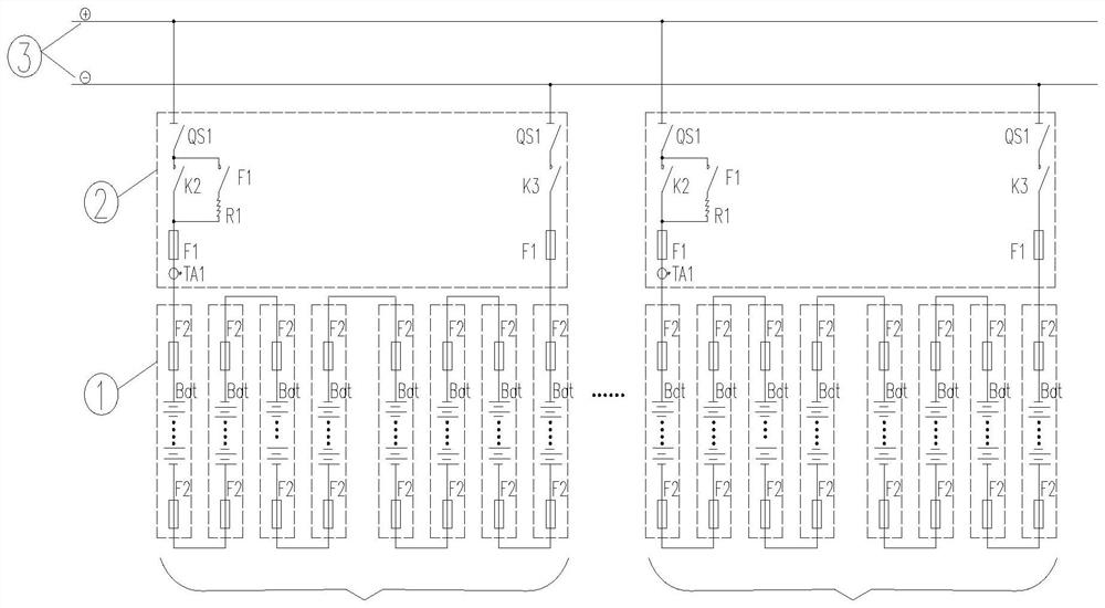
[0013] According to the future development trend of BESS, the capacity of the single battery module will further increase, which means that the level of short-circuit current will further increase, and the rated current will also exceed 450A, which means that the existing fuse equipment is very important for the future development trend. Difficult to adapt

Method used


Image

  • Implementation method of electronic power switch device for BESS system
  • Implementation method of electronic power switch device for BESS system
  • Implementation method of electronic power switch device for BESS system

Examples


Embodiment Construction

[0030] The present invention will be further described below in conjunction with the accompanying drawings.

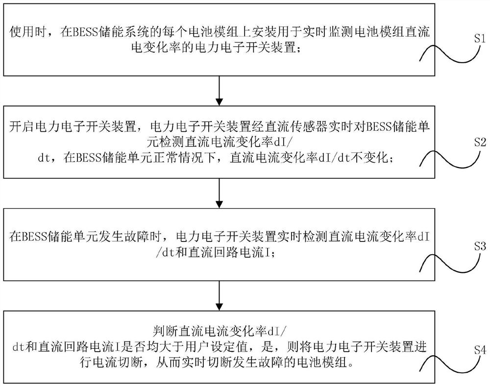
[0031] see figure 2 As shown, the present invention provides a method for realizing a power electronic switchgear for a BESS system, the method comprising the following steps:

[0032] Step S1, when in use, install a power electronic switch device for real-time monitoring of the battery module DC change rate on each battery module of the BESS energy storage system;

[0033] Step S2, turn on the power electronic switch device, the power electronic switch device detects the DC current change rate dI / dt of the BESS energy storage unit in real time through the DC sensor, and the DC current change rate dI / dt does not change under the normal condition of the BESS energy storage unit;

[0034] Step S3, when the BESS energy storage unit fails, the power electronic switch device detects the DC current change rate dI / dt and the DC loop current I in real time;

[0035] Step S4...


PUM


Abstract

The invention provides an implementation method of a power electronic switch device for a BESS system, and the method comprises the following steps: S1, installing a power electronic switch device for monitoring the direct current change rate of a battery module in real time on each battery module of the BESS system during use; s2, a power electronic switch device is started, the power electronic switch device detects the direct current change rate dI / dt of the BESS energy storage unit in real time through a direct current sensor, and under the normal condition of the BESS energy storage unit, the direct current change rate dI / dt does not change; s3, when the BESS energy storage unit breaks down, the power electronic switch device detects the direct current change rate dI / dt and the direct current loop current I in real time; s4, whether the direct current change rate dI / dt and the direct current loop current I are both larger than a user set value or not is judged, and if yes, current cutting-off is conducted on the power electronic switch device; according to the invention, when the BESS energy storage system has a fault, the fault part can be effectively removed in real time, and the safety performance is ensured.

Description

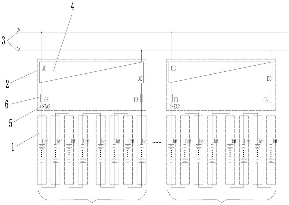
technical field [0001] The invention relates to the technical field of battery detection in energy storage power stations, in particular to a method for realizing a power electronic switchgear used in a BESS system. Background technique [0002] The battery system part of the energy storage power station consists of cells to form modules, modules to form battery modules, and battery modules to form a battery energy storage system (BESS). There are two topologies: low-voltage parallel collection and medium-high voltage series direct connection. At present, low-voltage parallel connection is the mainstream method. The voltage of the BESS system is mostly 1000V and 1500V, and the power is exchanged with the AC grid through the PCS. [0003] When a short-circuit fault occurs in the BESS, the fault current rises very rapidly. According to the actual measurement provided by the leading battery company, when the capacity of the single battery module is 372.7kWh, the peak value of ...

Claims


Application Information

Patent Timeline
Patent Type & Authority Applications(China)
IPC IPC(8): H02H7/26H02H3/087H02H3/06
Inventor 彭花娜陈翠勤刘勇李国伟王劲军
Owner FUJIAN YONGFU POWER ENG
Learn More