Supercharge Your Innovation With Domain-Expert AI Agents!

A capacitive charging type touch button detection circuit and detection method

A capacitor charging and detection circuit technology, which is applied to electrical components, electronic switches, pulse technology, etc., can solve problems such as misjudgment, and achieve the effects of strong practicability, improved detection accuracy, and simple detection methods

Active Publication Date: 2022-05-27
NANJING QINHENG MICROELECTRONICS CO LTD
View PDF0 Cites 0 Cited by
  • Summary
  • Abstract
  • Description
  • Claims
  • Application Information

AI Technical Summary

Problems solved by technology

[0007] Purpose of the invention: In order to solve the problem in the prior art that the capacitive charging type touch key is affected by the interference source and easily lead to misjudgment in the sampling and holding stage, the present invention provides a capacitive charging type touch key detection circuit and detection method

Method used


Image

  • A capacitive charging type touch button detection circuit and detection method
  • A capacitive charging type touch button detection circuit and detection method
  • A capacitive charging type touch button detection circuit and detection method

Examples


Embodiment 1

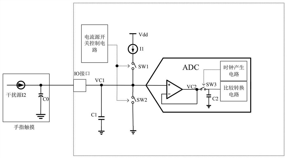
[0035] A capacitive charging type touch key detection circuit, such as image 3 As shown, it includes a detection interface, a fixed parasitic capacitance C1, a current source, a first switch SW1, a second switch SW2 and an ADC module, and the fixed parasitic capacitance C1 is connected to the detection interface. SW1 is a charging switch, and its two ends are respectively connected to a current source and a detection interface. SW2 is a discharge switch, and its two ends are respectively connected to the ground and the detection interface.

[0036] The ADC module is connected to the detection interface, and the ADC module includes a voltage follower, a sampling switch SW3, a capacitor C2, a clock generation circuit and a comparison conversion circuit. The non-inverting input end of the voltage follower is connected to the detection interface, the inverting input end of the voltage follower is connected to the output end, one end of the sampling switch is connected to the out...

Embodiment 2

[0046] Embodiment 2 also adds a bandpass filter on the basis of Embodiment 1, such as Figure 5 , the band-pass filter is located in the ADC module, the input end of the band-pass filter is connected to the output end of the voltage follower, and the output end is connected to the sampling switch. During the touch process, the band-pass filter does not affect the voltage follow of the VC2 node to the VC1 node, and at the same time filters out the power frequency interference introduced by the low-frequency alternating current, as well as the high-frequency interference such as wireless communication, and reduces the influence of the interference source in the touch button sampling stage. However, it is required that the band-pass filter cannot affect the normal charging of the capacitor whether it is touched or not, so its cut-off frequency is required.

[0047] like Figure 5 shown is an implementation of a bandpass filter, other circuits can also be used to achieve the same...


PUM


Abstract

The invention discloses a capacitive charging type touch button detection circuit and a detection method. The detection circuit includes a detection interface, a fixed parasitic capacitance C1, a current source, a first switch, a second switch and an ADC module, and the fixed parasitic capacitance C1 is connected to the detection interface. The two ends of the first switch are respectively connected to the current source and the detection interface, and the two ends of the second switch are respectively connected to the ground and the detection interface. The ADC module is connected to the detection interface. The ADC module includes a sampling switch and a clock generation circuit. The clock generation circuit is connected to the first switch. The first switch, the second switch and the sampling switch are connected, and the clock generation circuit is used to control the opening and closing of the first switch, the second switch and the sampling switch. The invention weakens the influence of the interference source on the detection of the touch key, and improves the detection accuracy and efficiency of the touch key.

Description

technical field [0001] The invention relates to the field of integrated circuit design, in particular to a capacitive charging type touch key detection circuit and a detection method. Background technique [0002] Capacitive charging touch keys have the characteristics of fast sampling conversion and low hardware consumption, but compared with other touch key types, they also have the disadvantage of being more sensitive to interference sources introduced by human touch. [0003] The traditional capacitive charging type touch key structure, such as figure 1 As shown, the fixed capacitance of the IO interface is C1, the charging current source of the touch button is I1, the switch control circuit controls the switches SW1 and SW2 to charge or discharge the capacitance, and the finger touch is equivalent to a touch equivalent capacitance C0 and an interference current source I2, ADC quantizes the voltage on the IO interface. [0004] like figure 2 , when the button is not ...

Claims


Application Information

Patent Timeline
Patent Type & Authority Patents(China)
IPC IPC(8): H03K17/96
Inventor 黄鹤
Owner NANJING QINHENG MICROELECTRONICS CO LTD
Features
  • R&D
  • Intellectual Property
  • Life Sciences
  • Materials
  • Tech Scout
  • Unparalleled Data Quality
  • Higher Quality Content
  • 60% Fewer Hallucinations
Learn More