Steaming and baking all-in-one machine

An all-in-one machine, steaming and baking technology, which is applied to steam cooking utensils, roasters/barbecue grids, cooking utensils, etc., can solve the problems of large working noise of circulating fans, increased working noise of cooking devices, and small air volume, etc., to achieve increased Large effective sweeping area, improving cooking efficiency and ensuring airtightness

Pending Publication Date: 2022-04-08
NINGBO FOTILE KITCHEN WARE CO LTD
View PDF9 Cites 6 Cited by
  • Summary
  • Abstract
  • Description
  • Claims
  • Application Information

AI Technical Summary

Problems solved by technology

In addition, in the rotating state of the circulating fan, the rotating shaft will constantly rub against the bearing sleeve, etc., so that the working noise of the circulating fan is relatively large, which in turn increases the overall working noise of the cooking device
[0004] In addition, the existing circulating fans generally have the problem of small air volume, which affects the flow volume and flow speed of the air in the inner tank, and then affects the cooking effect of the cooking device

Method used


Image

  • Steaming and baking all-in-one machine
  • Steaming and baking all-in-one machine
  • Steaming and baking all-in-one machine

Examples


Embodiment 1

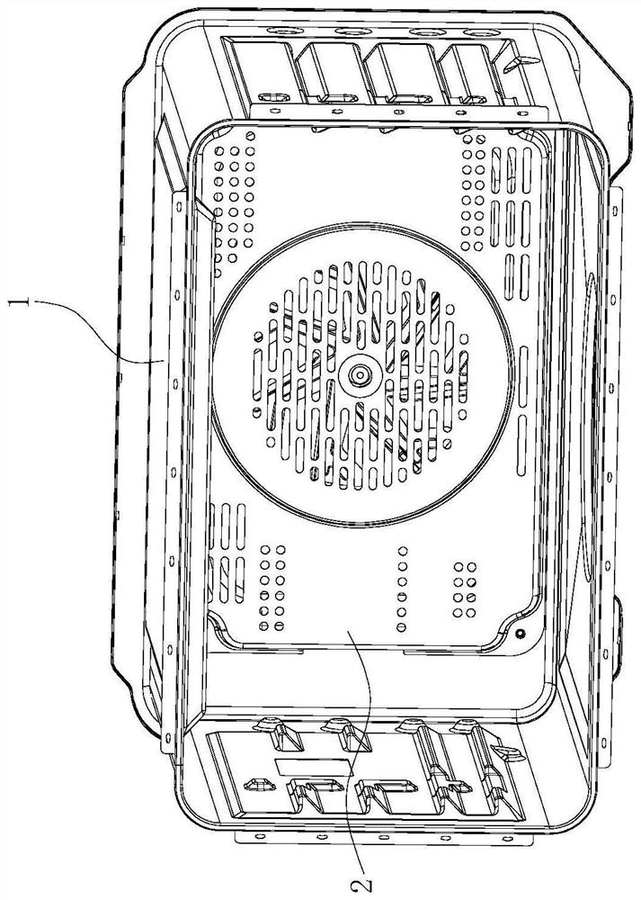
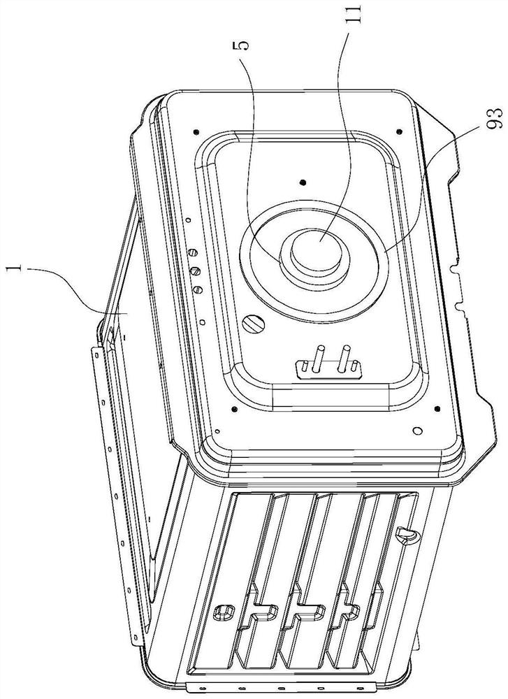
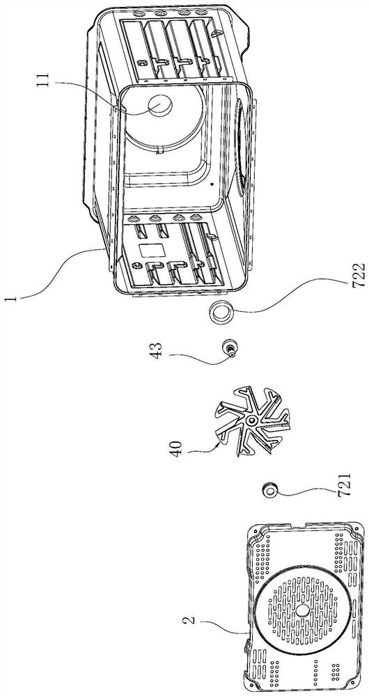
[0044] Such as Figure 1-8 as well as Figure 11 and Figure 12 As shown, a steaming and baking integrated machine includes an inner container 1, a circulating fan 4 is installed on the back plate of the inner container 1, and a hot air baffle 2 is arranged on the rear side of the inner cavity of the inner container 1, and the hot air baffle 2 The hot air chamber 20 is surrounded by the backboard of the inner container 1 , the impeller 40 of the above-mentioned circulating fan 4 is located in the hot air chamber 20 , and the outer periphery of the impeller 40 is provided with a heating pipe 3 .

[0045] The circulation fan 4 further includes a rotating shaft 43 extending forward and backward, and the middle part of the rotating shaft 43 is connected to the central shaft hole 411 of the hub plate 41 . In the prior art, the rotating shaft 43 of the circulating fan 4 is generally set on the inner tank 1 through a hole on the back plate of the inner tank 1 , and the opening of t...

Embodiment 2

[0057] Such as Figure 9 , Figure 10 as well as Figure 12 As shown, the difference from Embodiment 1 is that in this embodiment, the inner peripheral surface of the stator 5 and the outer peripheral surface of the rotor 6 are both shaped surfaces. By designing the special-shaped surface, an auxiliary force can be provided for the interaction between the stator 5 and the rotor 6, so as to avoid excessive coil load in the stator 5 during the start-up of the circulation fan 4 and prolong the service life of the stator 5. Specifically, the inner peripheral surface of the stator 5 and the outer peripheral surface of the rotor 6 are tooth-shaped, which can better provide auxiliary force for the interaction between the stator 5 and the rotor 6 .


PUM


Abstract

The invention relates to a steaming and baking all-in-one machine which comprises an inner container, a circulating fan is installed on a back plate of the inner container, a hot air baffle is arranged on the rear side of an inner cavity of the inner container, a hot air chamber is defined by the hot air baffle and the back plate of the inner container, an impeller of the circulating fan is located in the hot air chamber, and a heating pipe is arranged on the periphery of the impeller. The circulating fan further comprises a rotating shaft extending front and back, the middle of the rotating shaft is connected into a central shaft hole of the impeller in a penetrating mode, a rotor is arranged at the rear end of the rotating shaft, and a stator capable of interacting with the rotor to drive the rotating shaft to rotate is arranged on the rear surface of the inner container back plate. The rotating shaft can be driven to rotate through interaction of the stator and the rotor inside and outside the inner container, so that the inner container does not need to be provided with holes, the air tightness of the inner container is guaranteed, and the cooking efficiency is improved, especially in steaming cooking.

Description

technical field [0001] The invention relates to the field of cooking devices, in particular to an integrated steaming and roasting machine. Background technique [0002] Cooking devices with roasting functions such as electric ovens and steam-baking machines are generally equipped with a hot air baffle on the rear side of the inner cavity of the inner tank. The hot air baffle and the back plate of the inner tank form a hot air chamber. A circulating fan is installed, and the impeller of the circulating fan is located in the hot air chamber, and a heating pipe is arranged on the outer periphery of the impeller. During the cooking process, the circulating fan rotates, and the gas in the inner tank enters the hot air chamber through the air inlet on the hot air baffle, and the gas entering the hot air chamber is heated and passes through the air outlet on the hot air baffle under the action of the centrifugal force of the impeller. Return to the inner tank. [0003] The exist...

Claims


Application Information

Patent Timeline
IPC IPC(8): A47J27/00A47J27/04A47J37/06
CPCY02P60/80
Inventor 王丁谭万福郑鑫
Owner NINGBO FOTILE KITCHEN WARE CO LTD
Why Eureka
Try Eureka