

Solid tire assembling equipment
A solid tire and assembly equipment technology, applied in tire installation, tire parts, transportation and packaging, etc., can solve the problems of high tire damage rate and uneven force on the rim, so as to avoid damage to the tire, apply uniform pressure and avoid impact Effect
- Summary
- Abstract
- Description
- Claims
- Application Information
AI Technical Summary
Problems solved by technology
Method used
Image

Examples
Embodiment
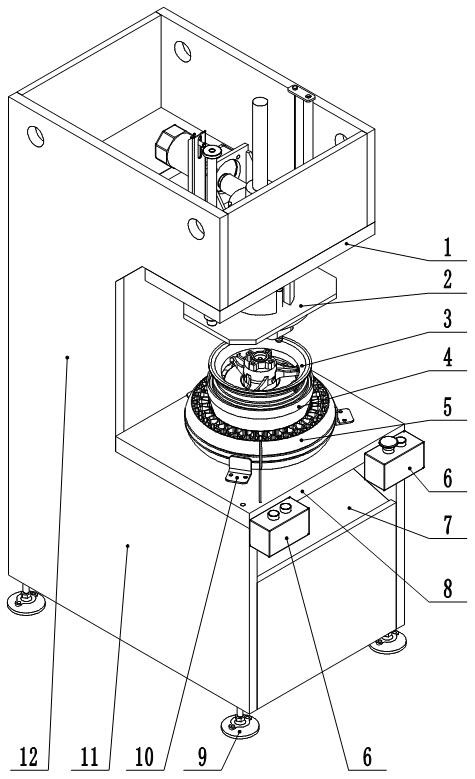
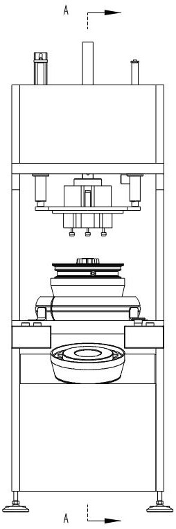
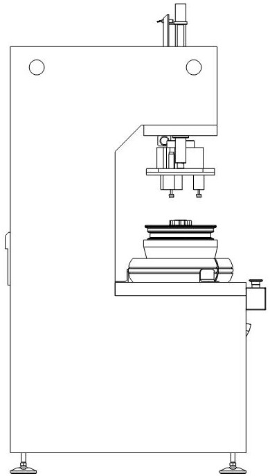
[0039] A solid tire assembly equipment, the structure of the applicable wheel 3 is: a number of spokes are provided between the rim and the hub, and there are intervals between adjacent spokes. The wheel 3 in this embodiment includes 3 spokes. The solid tire assembly equipment in this embodiment includes a C-shaped frame, a lifting head assembly 2 , a core expansion mold 4 and a controller 6 .
[0040] The C-shaped frame includes an integrally welded base 11, a column 12, and a top box. The base 11 is provided with a workbench 8. The workbench 8 is used to place solid tires 5. The workbench 8 is provided with a drop die hole 801. The hole 801 is used to pass the expansion core mold 4; the base 11 is also provided with a drop die ramp 7, and the drop die ramp 7 is located below the drop die hole 801, and is used to receive the expansion core die falling from the drop die hole 801 4. A soft material is laid on the upper surface of the inclined platform 7 of the falling mold. In ...
PUM
 Abstract
Description
Claims
Application Information