
Air switch limiting bolt with heated bouncing function

A technology of limit bolt and air switch, used in thermal switch parts, fire rescue and other directions, can solve the problem of inability to extinguish fire with air switch, and achieve the effect of avoiding fire spread, excellent control response speed, and avoiding delay.

Pending Publication Date: 2022-04-08
江峰
View PDF0 Cites 0 Cited by
  • Summary
  • Abstract
  • Description
  • Claims
  • Application Information

AI Technical Summary

Problems solved by technology

[0006] The purpose of the present invention is to provide an air switch stopper with the function of being heated and popped up, so as to solve the problem that the air switch cannot be extinguished immediately after the air switch short-circuits and spontaneously ignites

Method used


Image

  • Air switch limiting bolt with heated bouncing function
  • Air switch limiting bolt with heated bouncing function
  • Air switch limiting bolt with heated bouncing function

Examples


Embodiment

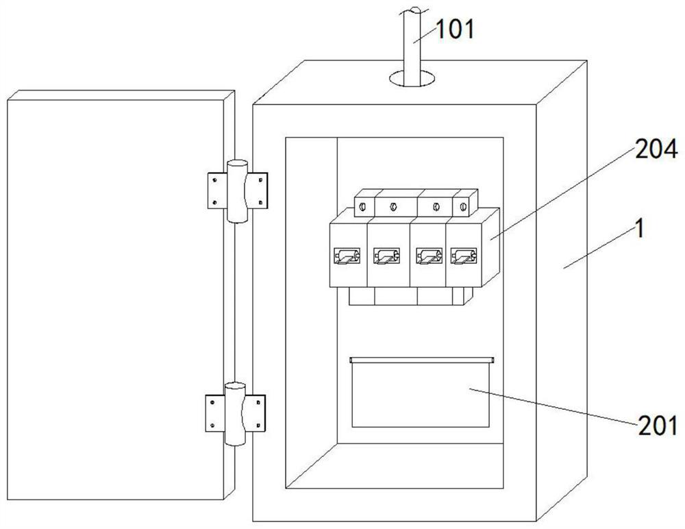
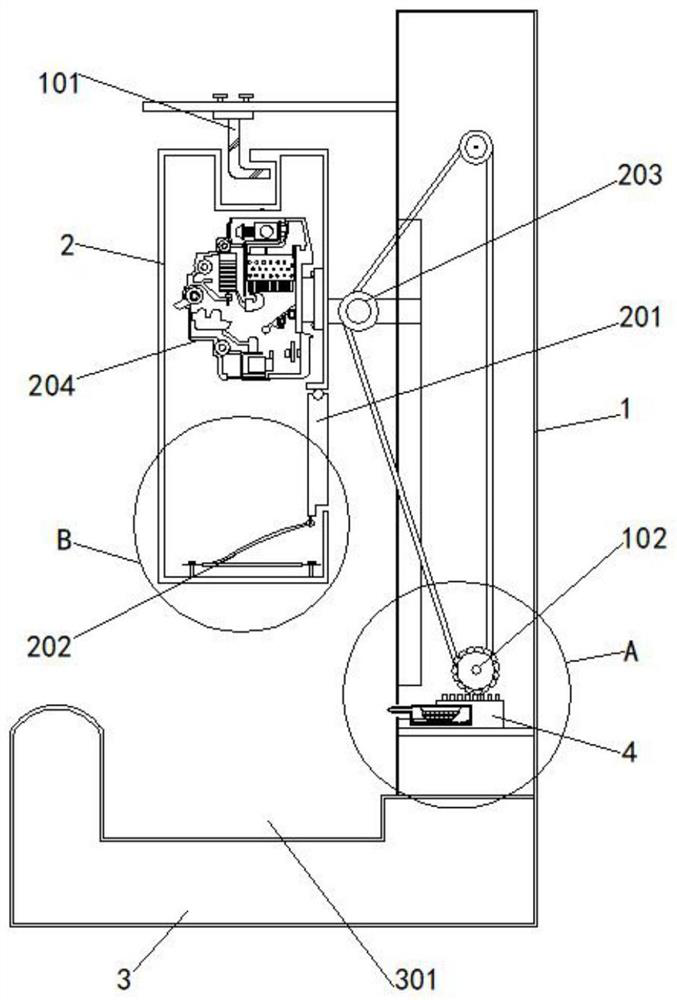
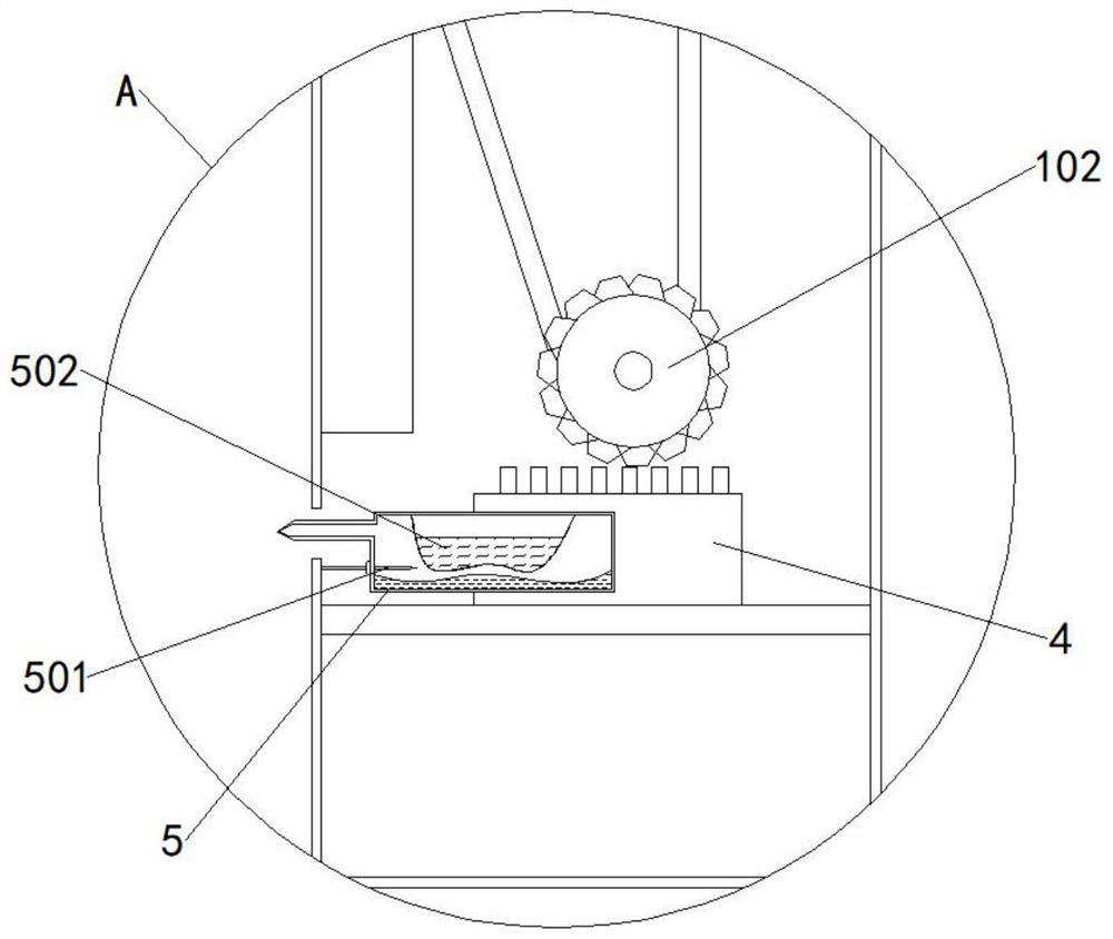
[0029] as attached figure 1 to attach Image 6 Shown:

[0030] The present invention provides a space-opening limit bolt with the function of popping up when heated, and the space-opening space-limiting bolt with the function of popping up when heated includes an installation and fixing block 1; inside the installation and fixing block 1, a fire extinguishing mechanism and a heat triggering mechanism are arranged;

[0031] Wherein, the heat trigger mechanism includes: L shape memory alloy limit bolt 101, toothed steel wire wheel 102, electric meter box 2, steel wire wheel 203, air switch 204, base 3, base groove 301, toothed slider 4;

[0032] The top of the fixing block 1 is fixedly installed with an L shape memory alloy limit bolt 101, and the meter box 2 is slidably installed on one side of the installation fixing block 1, and the L shape memory alloy limit bolt 101 fixes the meter box 2 on the top of the fixing block 1 On one side of the fixed block 1, an air switch 204 ...

Embodiment 2

[0038] The present invention also includes a heat opening mechanism, which includes a flip cover 201 and a butterfly bimetal 202;

[0039] A flip cover 201 is installed on one side of the bottom of the meter box 2, and a butterfly bimetal sheet 202 is fixedly installed on the bottom side of the meter box 2, and the butterfly bimetal sheet is movably connected to the flip cover 201. After the inside of the meter box 2 catches fire, the butterfly bimetal sheet will Sheet 202 encounters thermal deformation and drives flip cover 201 to turn up and one side of electric meter box 2 is opened to facilitate fire extinguishing.

[0040] The specific usage and function of this embodiment:

[0041]In the present invention, firstly, after the electric meter box 2 is affected by the surrounding environment and catches fire, in order to protect the air switch 204 from being damaged, the L shape memory alloy stopper 101 will become straight when heated, and the electric meter box 2 will no l...


PUM


Abstract

The invention provides an air switch limiting bolt with a heated bouncing function. The air switch limiting bolt comprises an installation fixing block. A fire extinguishing mechanism and a heat triggering mechanism are arranged in the mounting fixing block, the heat triggering mechanism comprises an L-shaped memory alloy limiting bolt, a toothed steel wire wheel, an electric meter box, a steel wire wheel, an air switch, a base, a base groove and a toothed sliding block, the L-shaped memory alloy limiting bolt is fixedly mounted at the top of the mounting fixing block, and the electric meter box is slidably mounted on one side of the mounting fixing block. An L-shaped memory alloy limiting bolt is arranged through an installation fixing block, the electric meter box is released and falls off when encountering an external fire environment, a toothed sliding block is driven to rotate through a steel wire wheel, so that the toothed sliding block slides, and a carbon dioxide fire extinguishing injection shell is pushed to puncture an air bag through a needle head; a sodium bicarbonate solution is subjected to a chemical reaction after encountering aluminum sulfate, a large amount of carbon dioxide is generated, the carbon dioxide fire extinguishing injection shell cannot contain carbon dioxide generated by the chemical reaction any more, and therefore the carbon dioxide is sprayed out under the air pressure for fire extinguishing.

Description

technical field [0001] The invention relates to the field of air release, in particular to an air release limiting bolt with the function of springing up when heated. Background technique [0002] The air switch is a switch that will automatically disconnect as long as the current in the circuit exceeds the rated current. It integrates control and multiple protection functions. Short circuit, severe overload and undervoltage protection. [0003] The air switch limit bolt that is bounced by heat is a device that can prevent the meter box from being affected by the outside world and cause the air switch to lose its function due to the impact of an external fire, thereby protecting the air switch from fire. [0004] The traditional meter box is often not found immediately after being ignited by external influences, resulting in uncontrollable flame spread and burning to the air switch, causing the air switch to lose its function, and thus unable to prevent short-circuit and ot...

Claims


Application Information

Patent Timeline
IPC IPC(8): H01H37/32H01H37/04A62C3/16
Inventor 江峰
Owner 江峰
Learn More