
Gas dust removal equipment based on gas flow rate

A technology of gas dust removal and gas flow rate, which is applied to the separation of dispersed particles, chemical instruments and methods, combined devices, etc., can solve the problems of affecting the normal use of equipment, poor dust removal effect, and pipe scaling, so as to avoid poor cleaning effect Good, easy to replace and prolong the service life

Active Publication Date: 2022-04-12
真一(上海)集成电路设备有限公司
View PDF7 Cites 0 Cited by
  • Summary
  • Abstract
  • Description
  • Claims
  • Application Information

AI Technical Summary

Problems solved by technology

[0003] However, when the existing equipment processes the exhaust gas, the flow rate of the gas exhaust will change with the change of the air pressure, causing the gas to quickly pass through the filter mechanism under high air pressure, resulting in ineffective removal of dust inside the gas. In the best case, if it is serious, it may cause fouling or blockage in the subsequent pipeline, which will affect the normal use of the equipment. Therefore, we propose a gas dedusting equipment based on the gas flow rate to solve the above problems

Method used


Image

  • Gas dust removal equipment based on gas flow rate
  • Gas dust removal equipment based on gas flow rate
  • Gas dust removal equipment based on gas flow rate

Examples


Embodiment Construction

[0027] The following will clearly and completely describe the technical solutions in the embodiments of the present invention with reference to the accompanying drawings in the embodiments of the present invention. Obviously, the described embodiments are only some, not all, embodiments of the present invention. Based on the embodiments of the present invention, all other embodiments obtained by persons of ordinary skill in the art without making creative efforts belong to the protection scope of the present invention.

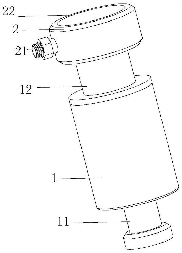
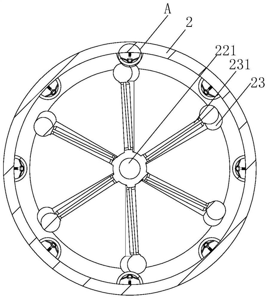
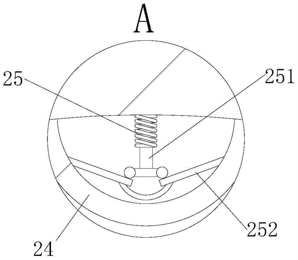
[0028] see Figure 1-7 , the present invention provides a technical solution: a gas dedusting device based on the gas flow rate, comprising an impurity removal pipe 1, the top of the impurity removal pipe 1 is fixedly connected with an air intake pipe 12, and the top of the air intake pipe 12 is fixedly connected with a drive plate 2, and the drive plate 2. There is a cavity inside. One side of the drive plate 2 is fixedly connected with a threaded pipe 21. Th...


PUM


Abstract

The invention discloses gas dedusting equipment based on gas flow rate, which comprises an impurity removal pipe, the top of the impurity removal pipe is fixedly connected with a gas inlet pipe, the top end of the gas inlet pipe is fixedly connected with a driving disc, the driving disc is internally provided with a cavity, one side of the driving disc is fixedly connected with a threaded pipe, the surface of the threaded pipe is sleeved with a nut in a threaded manner, and the driving disc is internally fixedly connected with a sealing cover. A connecting pipeline is fixedly connected to the bottom of the impurity removal pipe, a clamping block is fixedly connected to the bottom of the connecting pipeline, a pair of limiting discs is fixedly connected to the inner wall of the impurity removal pipe, and a plurality of arc-shaped grooves are formed in the surfaces of the limiting discs; compared with the prior art, air pressure near the extrusion shaft is changed, so that the extrusion shaft is expanded, the surface of a driving plate and the extrusion shaft can rub each other, a straight rod made of an activated carbon material can adsorb a part of small-particle impurities in the rotating process, and the pretreatment effect can be achieved; and the situation that dust and impurities are accumulated on the driving plate can be reduced, and the maintenance period of equipment can be prolonged.

Description

technical field [0001] The invention relates to the technical field of waste gas treatment, in particular to a gas dedusting device based on gas flow rate. Background technique [0002] Exhaust gas purification mainly refers to the work of treating industrial waste gas such as dust particles, flue gas smoke, odorous gas, and toxic and harmful gases generated in industrial places. Common waste gas purification includes factory smoke and dust waste gas purification, workshop dust waste gas purification, organic waste gas purification, waste gas odor purification, acid-base waste gas purification, chemical waste gas purification, etc. [0003] However, when the existing equipment processes the exhaust gas, the flow rate of the gas exhaust will change with the change of the air pressure, causing the gas to quickly pass through the filter mechanism under high air pressure, resulting in ineffective removal of dust inside the gas. In the best case, if it is serious, it may cause f...

Claims


Application Information

Patent Timeline
Patent Type & Authority Applications(China)
IPC IPC(8): B01D50/00
CPCY02A50/2351
Inventor 朱一帆
Owner 真一(上海)集成电路设备有限公司
Learn More