Biomass gas production tar circulating cleaning device

A cleaning device and biomass technology, applied in the direction of cleaning hollow objects, cleaning methods and appliances, chemical instruments and methods, etc., can solve problems that affect the normal use of pipelines and reduce the efficiency of biomass gas production

Inactive Publication Date: 2022-04-12
陈静茹
View PDF0 Cites 0 Cited by
  • Summary
  • Abstract
  • Description
  • Claims
  • Application Information

AI Technical Summary

Problems solved by technology

[0003] However, at present, biomass gas production is widely used in China. The gas contains tar, and the gas is transported through the fan pumping pipeline. The liquefied tar will accumulate on the inner wall of the pipeline, and the accumulation of too much tar will affect the normal use of the pipeline. At the same time, the existing Biomass gas production needs to be stopped when the pipeline is cleaned, which greatly reduces the efficiency of biomass gas production. Therefore, we propose a biomass gas production tar cycle cleaning device

Method used


Image

  • Biomass gas production tar circulating cleaning device
  • Biomass gas production tar circulating cleaning device
  • Biomass gas production tar circulating cleaning device

Examples


Embodiment 1

[0033] see Figure 1-9 , the present invention provides a technical solution:

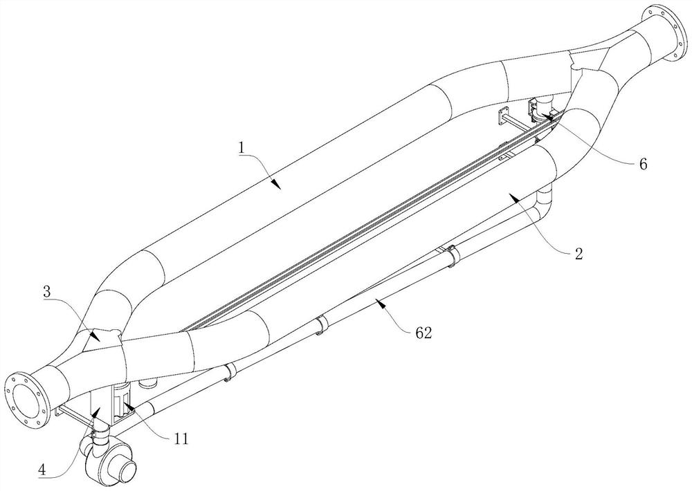
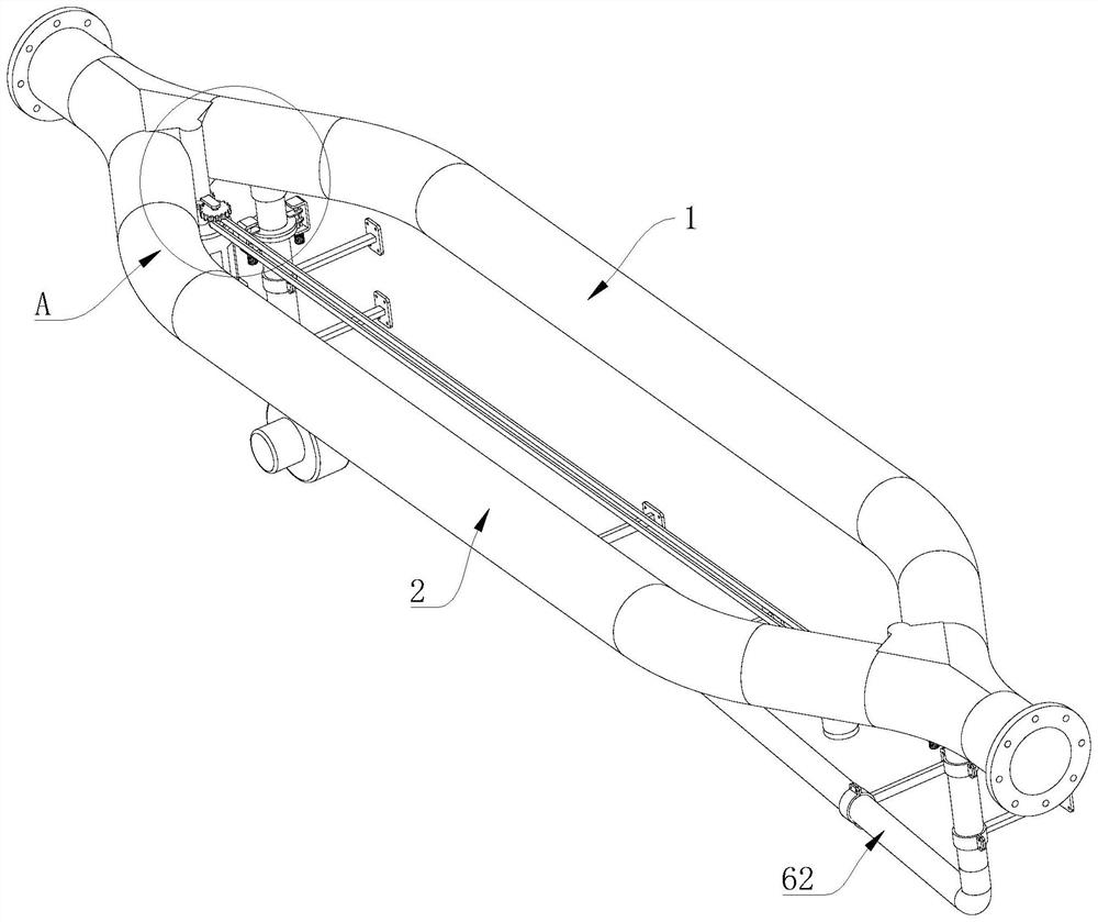
[0034] A biomass gas production tar cycle cleaning device, comprising a gas production pipeline 1, flanges are arranged at both ends of the gas production pipeline 1;

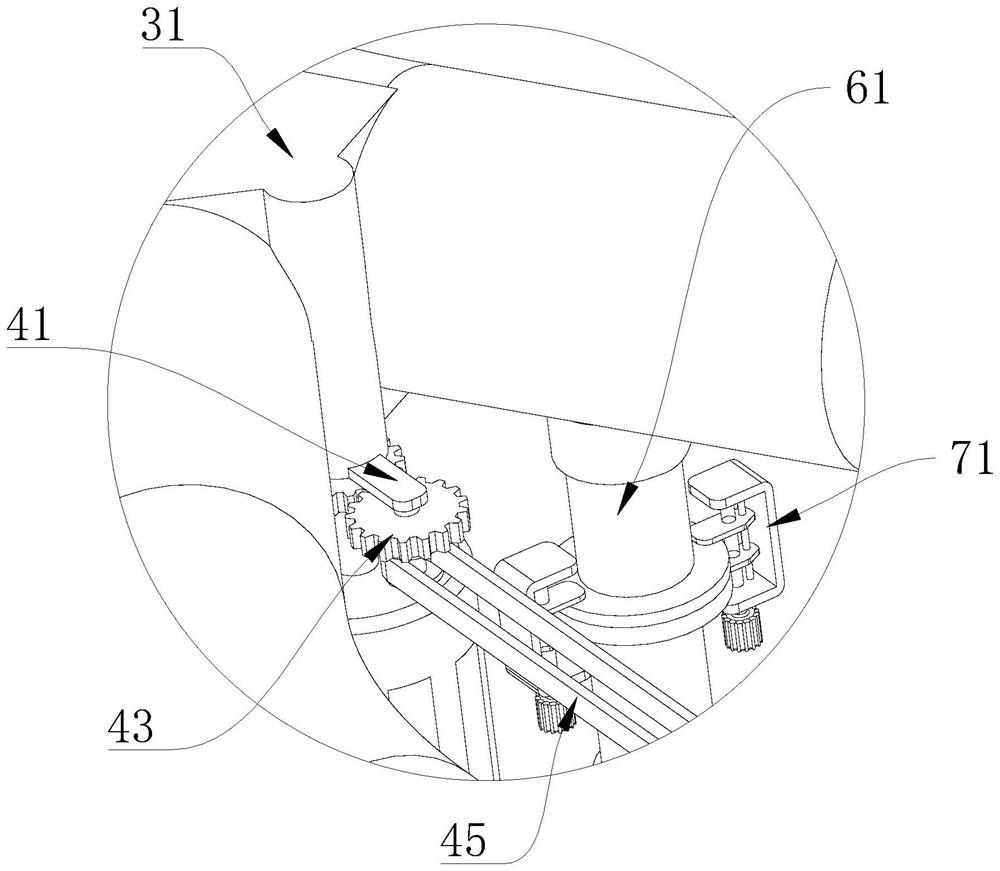
[0035] The gas-making pipeline 1 is provided with an auxiliary pipeline 2 that communicates with each other at both ends. The diameters of the gas-making pipeline 1 and the auxiliary pipeline 2 are the same. 31. The functional chamber 31 communicates with the gas-making pipeline 1 and the auxiliary pipeline 2. A main shaft 32 with one end extending to the outside of the functional chamber 31 is rotated in the functional chamber 31. A sealing plate 33 is arranged outside the main shaft 32. The sealing plate 33 is connected to the gas-making pipeline. Pipe 1 and auxiliary pipe 2 have the same inner diameter;

[0036] Both the inside of the gas pipeline 1 and the auxiliary pipeline 2 are provided with a fixed ring 34, and the sealing...

Embodiment 2

[0050] see Figure 1-10 , the present invention provides a technical solution:

[0051] A biomass gas production tar cycle cleaning device, comprising a gas production pipeline 1, flanges are arranged at both ends of the gas production pipeline 1;

[0052] The gas-making pipeline 1 is provided with an auxiliary pipeline 2 that communicates with each other at both ends. The diameters of the gas-making pipeline 1 and the auxiliary pipeline 2 are the same. 31. The functional chamber 31 communicates with the gas-making pipeline 1 and the auxiliary pipeline 2. A main shaft 32 with one end extending to the outside of the functional chamber 31 is rotated in the functional chamber 31. A sealing plate 33 is arranged outside the main shaft 32. The sealing plate 33 is connected to the gas-making pipeline. Pipe 1 and auxiliary pipe 2 have the same inner diameter;

[0053] Both the inside of the gas pipeline 1 and the auxiliary pipeline 2 are provided with a fixed ring 34, and the sealin...


PUM


Abstract

The biomass gas production tar circulating cleaning device comprises a gas production pipeline, and flanges are arranged at the two ends of the gas production pipeline; an auxiliary pipeline with the two ends communicated with each other is arranged on the gas making pipeline, switching pieces are arranged at the communicating positions of the gas making pipeline and the auxiliary pipeline, and a synchronizing piece is arranged between the two switching pieces, so that the two switching pieces can be driven to work synchronously through the synchronizing piece; the biomass gas production tar circulating cleaning device comprises a gas production pipeline and an auxiliary pipeline, connecting pipes are arranged on the outer sides of the two sides of the gas production pipeline and the outer side of the two sides of the auxiliary pipeline, internal threads are formed in the connecting pipes, and a cleaning mechanism is arranged between the two connecting pipes located on the same pipeline. When tar cleaning is needed, alternate use of the gas making pipeline and the auxiliary pipeline can be completed through the switching piece, and circulating cleaning of the gas making pipeline and the auxiliary pipeline can be achieved through the cleaning mechanism.

Description

technical field [0001] The invention relates to the technical field of a tar circulation cleaning device, in particular to a biomass gas production tar circulation cleaning device. Background technique [0002] In my country, biomass plays a pivotal role in energy consumption. It is second only to coal and becomes the second largest energy source in my country, accounting for 20% of total energy consumption. In rural energy consumption, biomass energy accounts for about 70% of domestic energy consumption. %, the traditional use of stoves for direct combustion is the main way of biomass energy utilization in my country at present. The energy utilization rate of this method is low, only 10-15%, and the energy loss is serious: the disorderly use and waste of biomass resources not only directly leads to Air pollution also seriously damages the ecological environment. At present, there are many methods for the development and utilization of biomass energy. Among the thermochemical ...

Claims


Application Information

Patent Timeline
IPC IPC(8): B08B9/032
Inventor 陈静茹
Owner 陈静茹
Why Eureka
Try Eureka