Spring claw forming and drawing equipment for fire hose and use method of spring claw forming and drawing equipment

A technology for drawing equipment and fire hoses, applied in the field of spring claw processing, can solve the problems of manpower and time cost, inability to rapidly process spring claw at multiple stations, and low processing efficiency.

Inactive Publication Date: 2022-04-12
重庆狼牙安防器材有限公司
View PDF2 Cites 0 Cited by
  • Summary
  • Abstract
  • Description
  • Claims
  • Application Information

AI Technical Summary

Problems solved by technology

[0005] The processing process of the spring claw products is too cumbersome in terms of sawing, milling and drilling, which requires a lot of manpower and time costs
It is not possible to perform multi-station rapid processing on the spring claw, and the processing efficiency is low

Method used


Image

  • Spring claw forming and drawing equipment for fire hose and use method of spring claw forming and drawing equipment
  • Spring claw forming and drawing equipment for fire hose and use method of spring claw forming and drawing equipment
  • Spring claw forming and drawing equipment for fire hose and use method of spring claw forming and drawing equipment

Examples


Embodiment 1

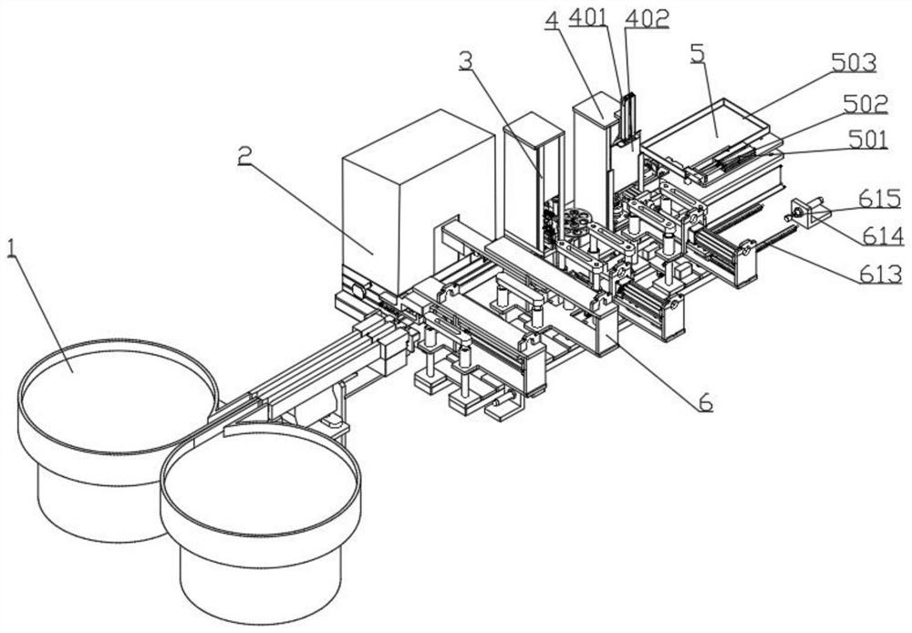
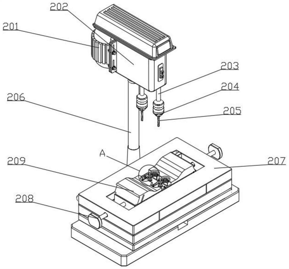
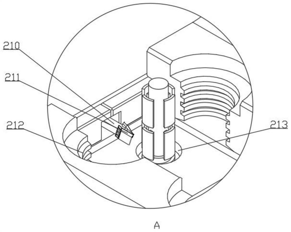
[0048] A spring claw forming and drawing equipment for a fire hose, comprising a blanking part 1, a drilling part 2, a riveting part 3, a dividing part 4, a collecting part 5 and a picking part 6, a blanking part 1, a drilling part 2, The riveting part 3, the dividing part 4, and the collecting part 5 are arranged at intervals on one side of the picking part 6, and the picking part 6 picks up parts and cooperates with the blanking part 1, the drilling part 2, the riveting part 3, the dividing part 4, and the collecting part 5. Line multi-process processing.

[0049] The present invention includes a blanking part 1, a drilling part 2, a riveting part 3, a dividing part 4, a collecting part 5 and a pick-up part 6. The position of the workpiece is adjusted and placed by the blanking part, which is convenient for the pick-up part 6 to quickly pick up the workpiece. Picking, the drilling part 2, the riveting part 3, the dividing part 4, and the collecting part 5 are arranged at int...

Embodiment 2

[0061] A spring claw forming and drawing equipment for a fire hose, comprising a blanking part 1, a drilling part 2, a riveting part 3, a dividing part 4, a collecting part 5 and a picking part 6, a blanking part 1, a drilling part 2, The riveting part 3, the dividing part 4, and the collecting part 5 are arranged at intervals on one side of the picking part 6, and the picking part 6 picks up parts and cooperates with the blanking part 1, the drilling part 2, the riveting part 3, the dividing part 4, and the collecting part 5. Line multi-process processing.

[0062]The present invention includes a blanking part 1, a drilling part 2, a riveting part 3, a dividing part 4, a collecting part 5 and a pick-up part 6. The position of the workpiece is adjusted and placed by the blanking part, which is convenient for the pick-up part 6 to quickly pick up the workpiece. Picking, the drilling part 2, the riveting part 3, the dividing part 4, and the collecting part 5 are arranged at inte...


PUM


Abstract

The invention relates to the technical field of spring claw machining, in particular to fire hose spring claw forming and drawing equipment which comprises a discharging part, a drilling part, a riveting part, a dividing part, a collecting part and a picking part, and the discharging part, the drilling part, the riveting part, the dividing part and the collecting part are distributed on one side of the picking part at intervals. And the pickup part picks up parts to cooperate with the feeding part, the drilling part, the riveting part, the dividing part and the collecting part for wire feeding and multi-procedure machining. The problem that a large amount of manpower and time cost needs to be consumed due to the fact that the machining process of a spring claw product in the aspects of saw cutting machining, groove milling machining, drilling machining and the like is too tedious is solved. Multi-station rapid machining cannot be carried out on the spring claw, and the machining efficiency is low. The invention further provides a using method of the forming and drawing equipment for the spring pawl for the fire hose.

Description

technical field [0001] The invention relates to the technical field of spring claw processing, in particular to a spring claw forming and drawing equipment for a fire hose and a use method thereof. Background technique [0002] The Chinese utility model patent with the publication number CN202684196U discloses a forming broaches for quick connector spring claws for fire hoses and spring claw products, especially an innovative structural design that can save the processing process and improve the processing quality; the practical The new type of sawing process by the forming broach can save the traditional tedious steps such as sawing and milling the ring workpiece after the turning process, so it can save a lot of time and cost; Then, the utility model uses the sawing of the forming broach to form the rounded corner groove, so that the inclined intersection surfaces of the formed ends of each spring claw product can generate a rounded corner at one time, so that the spring c...

Claims


Application Information

Patent Timeline
Patent Type & Authority Applications(China)
IPC IPC(8): B23P23/00B23Q7/00B23Q7/04
Inventor 杨阳况巧李新莲况锡洪李威霆李家豪
Owner 重庆狼牙安防器材有限公司
Why Eureka
Try Eureka