Machining process and device of gear pump

A processing device and processing technology technology, which is applied in the direction of positioning devices, metal processing equipment, metal processing machinery parts, etc., can solve the problems of cumbersome processing of pump cores and low processing efficiency, so as to speed up processing efficiency, improve processing efficiency, reduce The effect of retention times

Active Publication Date: 2022-04-12
淮安万科液压机械有限公司
View PDF10 Cites 0 Cited by
  • Summary
  • Abstract
  • Description
  • Claims
  • Application Information

AI Technical Summary

Problems solved by technology

[0003] During the machining process of the gear pump, it is necessary to use a milling cutter to cut the inner hole and the outer circular wall of the pump core. However, in the prior art, since the positioning mechanism directly fixes the pump core, after machining the inner hole of t

Method used


Image

  • Machining process and device of gear pump
  • Machining process and device of gear pump
  • Machining process and device of gear pump

Examples


Embodiment 1

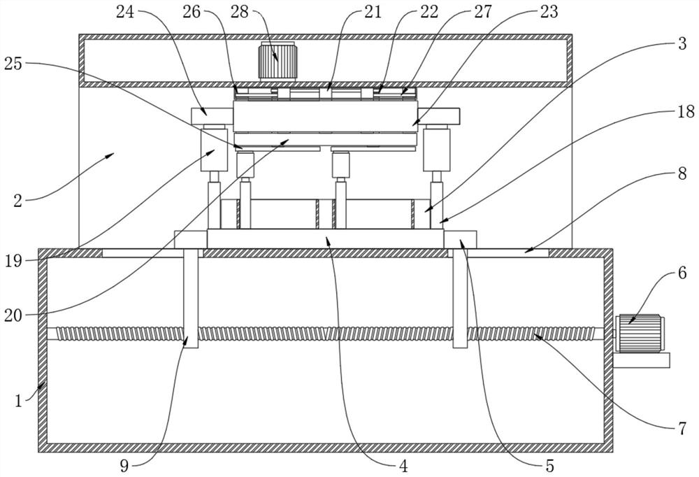
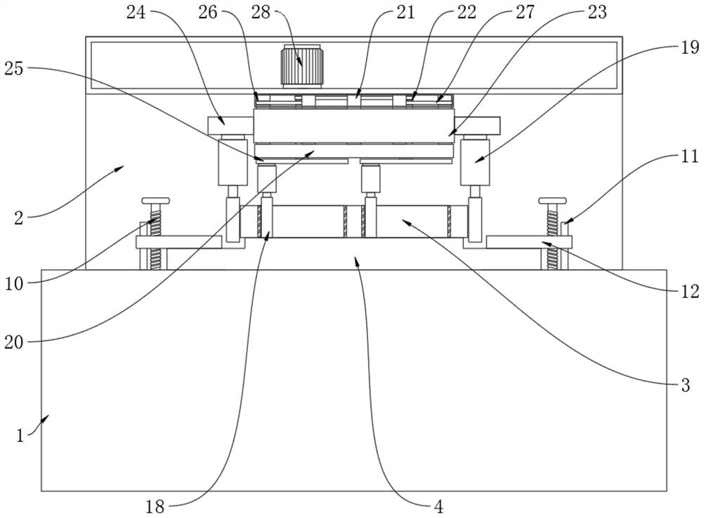
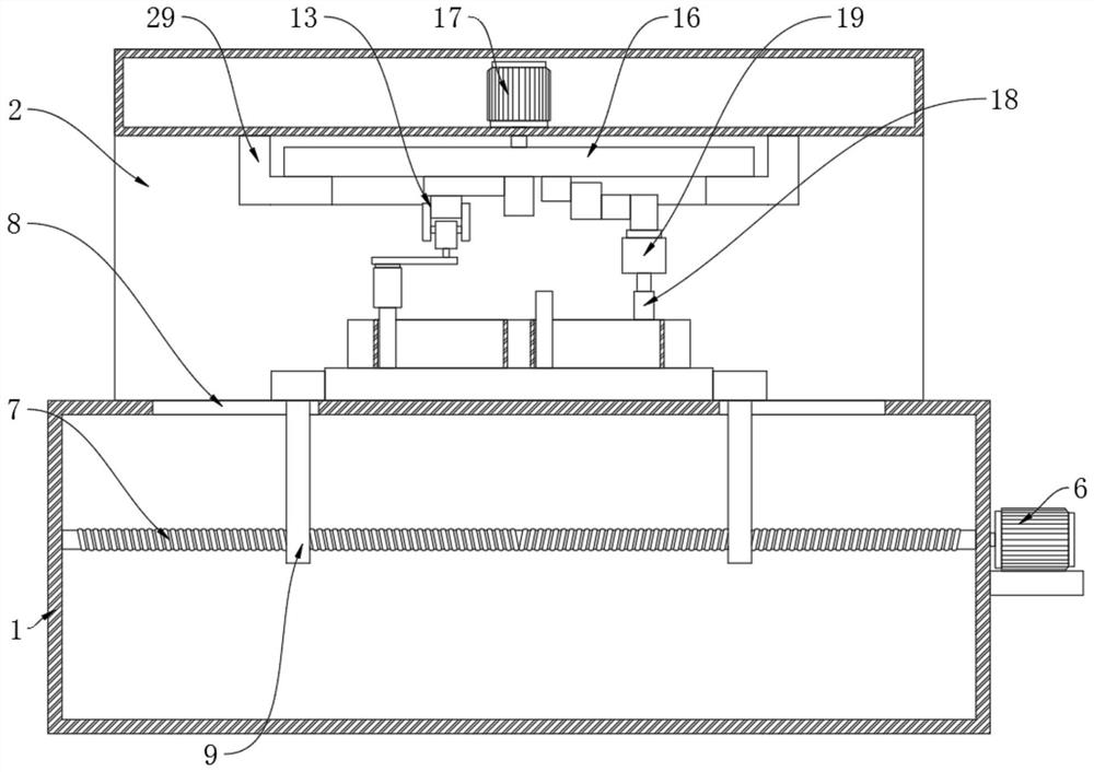
[0032] Please refer to Figure 1 to Figure 3 , a processing device for a gear pump, comprising a processing table 1, a frame 2 is fixedly installed on the top of the processing table 1, a transmission mechanism is provided on the frame 2, a cutting mechanism is provided on the transmission mechanism, and the transmission mechanism is used to drive the cutting mechanism to move , the workbench is also provided with a pump core 3, the bottom of the pump core 3 is glued to the retainer 4 by colloid, and the outside of the retainer 4 is provided with a positioning mechanism, which is used to fix the retainer 4; the cutting mechanism is at least provided with Two, two cutting mechanisms cut the inner hole and the outer wall of the pump core 3 respectively.

[0033] The positioning mechanism can clamp and fix both sides of the retainer 4:

[0034] Specifically, the positioning mechanism includes two clamping plates 5, the outside of the processing table 1 is provided with a positio...

Embodiment 2

[0048] Furthermore, the present invention provides another embodiment: since the retainer 4 is bonded to the bottom of the pump core 3 with colloid, and then the positioning mechanism is used to position the retainer 4, thereby ensuring that the positioning mechanism will not block the external cutting mechanism from The pump core 3 is processed, therefore, multiple cutting mechanisms can be set to process the pump core 3 synchronously,

[0049] Specifically, such as figure 1 and figure 2 , the cutting mechanism comprises a milling cutter 18 and a power motor 19, the output shaft of the power motor 19 is fixedly mounted with a milling cutter 18, and three cutting mechanisms are arranged, and the three cutting mechanisms move synchronously for processing;

[0050] It should be noted that, in the embodiment of the present invention, multiple milling cutters 18 operate synchronously, which can realize synchronous cutting and processing of the two inner holes and the outer wall ...

Embodiment 3

[0052] Further, the transmission mechanism includes two fixed blocks 20, a plurality of rotating shafts 21 and two power shafts 22 are arranged between the two fixed blocks 20, and a transmission belt 23 is installed between the outer sides of the plurality of rotating shafts 21, and the transmission belt 23 The transmission block 24 is fixedly installed, and the bottom ends of the two power shafts 22 extend downward through the fixed block 20, and the bottom ends of the power shafts 22 are fixedly installed with a circular rotating plate 25, and the centers of the two circular rotating plates 25 are respectively Corresponding to the center of the two inner holes of the pump core 3; the inner cavity of the upper fixed block 20 is provided with a deceleration motor 28, the output shaft of the deceleration motor 28 is fixedly connected to the end of one of the power shafts 22, and the two power shafts 22 The driving belt 27 is connected through the shaft disk 26, and the driving ...


PUM


Abstract

The invention discloses a machining process and device of a gear pump, relates to the technical field of gear pump manufacturing, and aims to provide the machining process and device of the gear pump, which simplify the machining process and accelerate the working efficiency, and is technically characterized in that a working table is further provided with a pump core, and the bottom of the pump core is bonded with a retention piece through colloid; a positioning mechanism is arranged on the outer side of the retention piece and is used for fixing the retention piece; the pump core machining device has the technical effects that the retention piece is bonded through the colloid, the retention piece is fixed through the positioning mechanism, when the machining position of the pump core is replaced, the pump core can be directly machined without loosening the fixation of the pump core, the machining efficiency is improved, and the machining cost is reduced. The pump core retention frequency is reduced, the pump core machining process is simplified, and the pump core machining efficiency is improved; as the positioning mechanism cannot stop the cutting mechanisms at different positions from running, a plurality of cutting mechanisms can be arranged for synchronous machining.

Description

technical field [0001] The invention relates to the technical field of gear pump manufacturing, in particular to a gear pump processing technology and device. Background technique [0002] The gear pump is a rotary pump that relies on the change and movement of the working volume formed between the pump cylinder and the meshing gear to deliver or pressurize the liquid. Two closed spaces are composed of two gears, the pump body and the front and rear covers. When the gears rotate, the volume of the space on the side where the gears are disengaged increases from small to large, forming a vacuum to suck the liquid, and the volume of the space on the side where the gears mesh changes from large to large. Small, and the liquid is squeezed into the pipeline. The suction chamber and the discharge chamber are separated by the meshing line of two gears. The pressure at the outlet of the gear pump depends entirely on the resistance at the outlet of the pump. [0003] During the mac...

Claims


Application Information

Patent Timeline
IPC IPC(8): B23Q3/08
Inventor 李国阳朱锦春
Owner 淮安万科液压机械有限公司
Why Eureka
Try Eureka