
Optical lens machining, polishing and grinding device

An optical lens and grinding device technology, applied in grinding devices, optical surface grinders, grinding drive devices, etc., can solve the problems of not having the function of dust suppression, affecting people's health, etc., and achieve the effect of improving grinding efficiency and reducing trouble

Inactive Publication Date: 2022-04-12
江西超联光电科技有限公司
View PDF1 Cites 1 Cited by
  • Summary
  • Abstract
  • Description
  • Claims
  • Application Information

AI Technical Summary

Problems solved by technology

However, due to the dust generated during grinding, the equipment does not have the function of dust reduction. People will inhale the dust in the body for a long time, which will affect people's health.

Method used


Image

  • Optical lens machining, polishing and grinding device
  • Optical lens machining, polishing and grinding device
  • Optical lens machining, polishing and grinding device

Examples


Embodiment 1

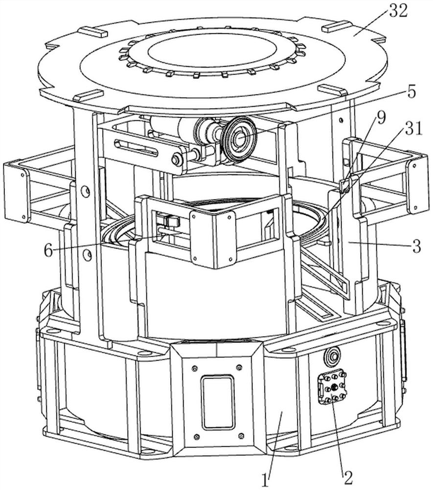
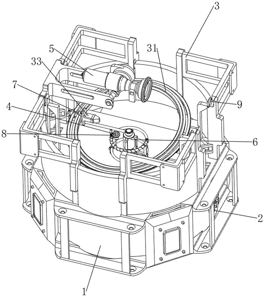
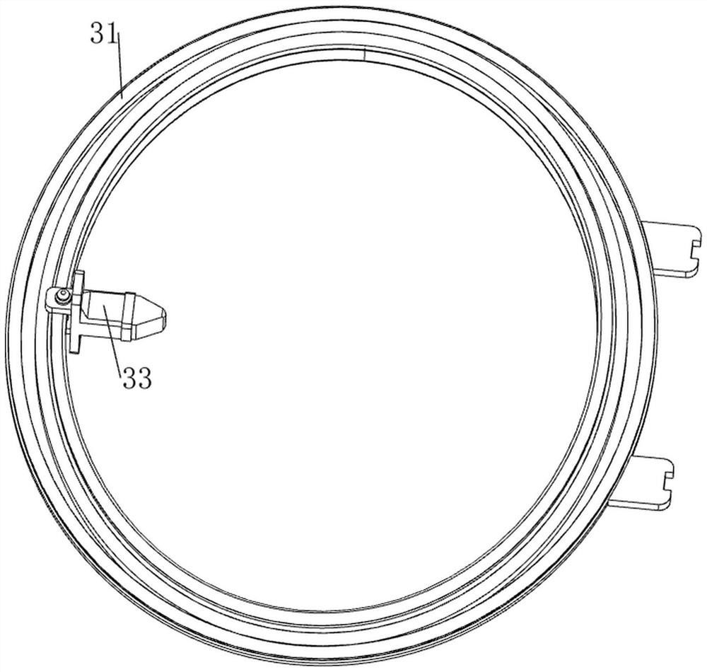
[0039] A polishing and grinding device for optical lens processing, referring to Figure 1-12 , including a water tank 1, a working frame 3, an elliptical orbit 31, a shielding part 32, a grinding part 33, a spraying mechanism 4, a feeding mechanism 5, a rotating mechanism 6 and an adjusting mechanism 7, a blocking block is placed on the front side of the water tank 1, and the water tank 1 The top is provided with a working frame 3, the inside of the working frame 3 is provided with an elliptical track 31, the top of the working frame 3 is provided with a blocking part 32, the inner side of the elliptical track 31 is slidingly provided with a grinding part 33, and the middle of the top of the water tank 1 is provided with a spraying mechanism 4. Frame 3 upper rear side is provided with unloading mechanism 5, is provided with rotating mechanism 6 on 4 parts of spraying mechanism, and elliptical track 31 rear side sliding type is provided with adjusting mechanism 7.

[0040] ref...

Embodiment 2

[0046] On the basis of embodiment 1, with reference to figure 2 , Figure 13 and Figure 14 , also includes a surrounding mechanism 8, the surrounding mechanism 8 includes a sliding sleeve 81, an electromagnet 82, an iron sliding plate 83, a sliding rod 84, a first spring 85, a second spring 86, a ring track 87 and a second distance sensor 88 , the front side of the top of the first fixed part 42 is provided with an annular track 87, and the rear side of the annular track 87 is slidingly provided with a sliding sleeve 81, which is connected with the spraying part 43, and the rear side of the sliding sleeve 81 is provided with an electromagnet 82, and the sliding sleeve Both sides are provided with slide bar 84 on the front and rear upper part of 81 rear sides, and slide bar 84 is provided with irony slide plate 83 slidingly, and irony slide plate 83 contacts with rotating bar 61, and between irony slide plate 83 and slide bar 84 A first spring 85 is connected between them, ...


PUM


Abstract

The invention relates to a polishing and grinding device, in particular to a polishing and grinding device for optical lens machining. The invention provides an optical lens machining, polishing and grinding device with a dust falling function. An optical lens machining, polishing and grinding device comprises a water tank, a working frame, an oval track, a shielding component, a grinding part, a spraying mechanism, a discharging mechanism and the like, a blocking block is placed on the front side of the water tank, the working frame is arranged at the top of the water tank, the oval track is arranged on the inner side of the working frame, the shielding component is arranged on the top of the working frame, and the grinding part is arranged on the inner side of the oval track in a sliding mode. A spraying mechanism for dust falling is arranged in the middle of the top of the water tank, and a discharging mechanism for conveying the lenses to make contact with the grinding part is arranged on the rear side of the upper portion of the working frame. The water pump is started to pump water in the water tank into the pipeline, the water is sprayed out by the spraying part for water spraying and dust falling, meanwhile, the lens can be cleaned, and dust on the lens is cleared away.

Description

technical field [0001] The invention relates to a polishing and grinding device, in particular to a polishing and grinding device for optical lens processing. Background technique [0002] The optical lens needs to go through a grinding process from the blank to the optical surface, but the existing technology has the problem that the lens cannot be processed continuously and the processing efficiency is low. [0003] The patent publication number is CN112775762A, which discloses a lens edge grinding equipment for industrial production, including a base and a support platform, the base is provided with a support platform; a motor is installed on the support platform; a rotating mechanism, the base is provided with a rotating mechanism , the rotating mechanism is connected with the output shaft of the motor; the clamping mechanism is provided on the base, and the clamping mechanism cooperates with the rotating mechanism; the grinding mechanism is provided on the base. Throug...

Claims


Application Information

Patent Timeline
Patent Type & Authority Applications(China)
IPC IPC(8): B24B13/00B24B37/11B24B37/27B24B37/34B24B47/12B24B47/22B24B49/00
Inventor 李燮民潘志明
Owner 江西超联光电科技有限公司
Learn More