Laser cutting equipment for high-end metal materials for biomedical treatment

A technology of biomedicine and metal materials, applied in laser welding equipment, metal processing equipment, welding/cutting auxiliary equipment, etc., can solve the problems of manual rotation, etc., and achieve the effect of reducing trouble and avoiding deviation

Inactive Publication Date: 2021-08-31
江西晖旭实业有限公司
View PDF0 Cites 2 Cited by
  • Summary
  • Abstract
  • Description
  • Claims
  • Application Information

AI Technical Summary

Problems solved by technology

[0004] In order to overcome the shortcomings of not being able to cut metal materials at equal lengths and manually turning the metal materials, the technical problem of the present invention is to provide a high-end biomedical laser cutting equipment for metal materials that cuts at equal lengths and reduces manual operations.

Method used


Image

  • Laser cutting equipment for high-end metal materials for biomedical treatment
  • Laser cutting equipment for high-end metal materials for biomedical treatment
  • Laser cutting equipment for high-end metal materials for biomedical treatment

Examples


Embodiment 1

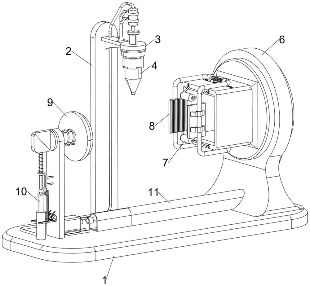
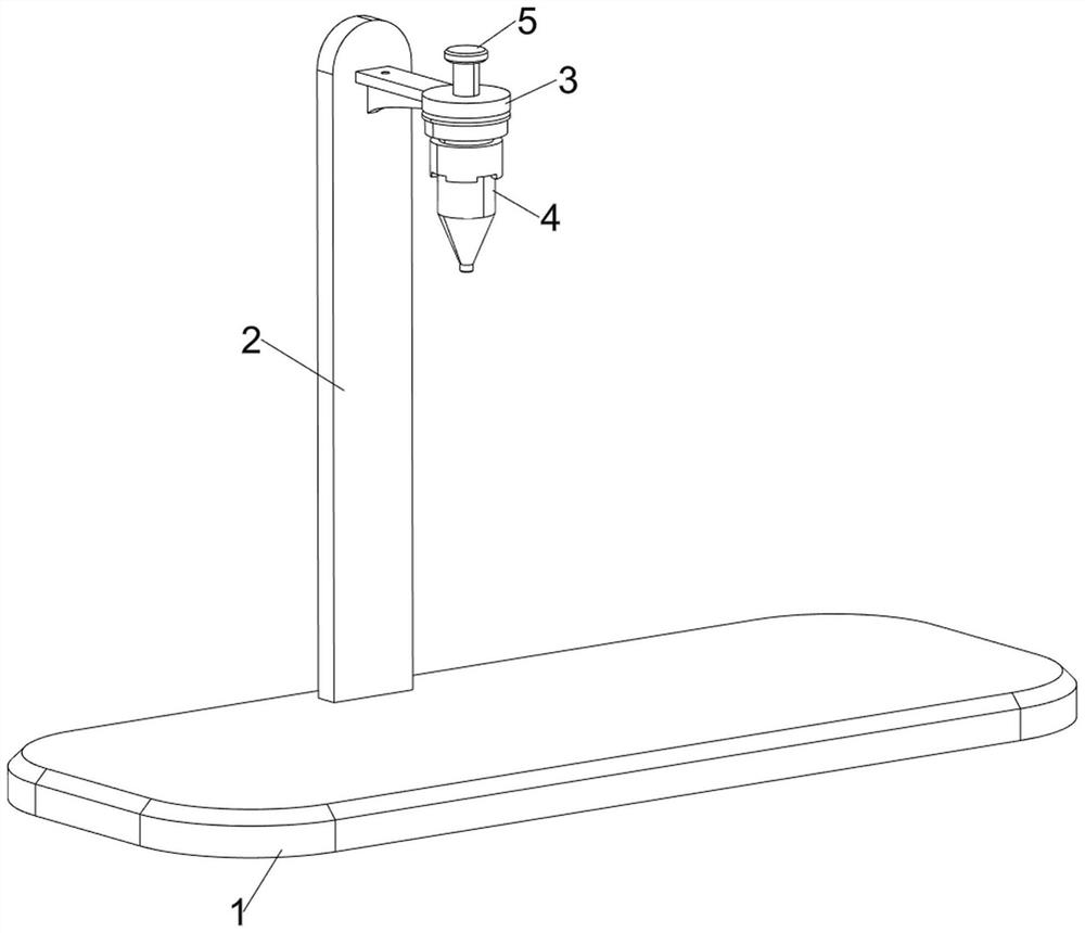
[0029] A high-end biomedical metal material laser cutting equipment, such as Figure 1-6 As shown, it includes a base plate 1, a first support plate 2, a first fixing plate 3, a laser head 4, a first slide bar 5, a placement mechanism 6 and a limit mechanism 7, and the rear side of the top of the base plate 1 is provided with a first support plate 2. There is a first fixed plate 3 on the front side of the upper part of the first support plate 2, and a first sliding rod 5 is provided on the front side of the first fixed plate 3. The laser head 4 is installed on the bottom of the first sliding rod 5, and the top of the bottom plate 1 The right side is provided with a placing mechanism 6, and the placing mechanism 6 is provided with a limit mechanism 7.

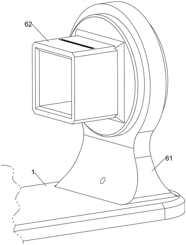
[0030] The placement mechanism 6 includes a support frame 61, a placement disc 62 and a first ring 63, the right side of the top of the base plate 1 is provided with a support frame 61, and the inner side of the upper part of th...

Embodiment 2

[0034] On the basis of Example 1, such as figure 1 , Figure 7 , Figure 8 , Figure 9 , Figure 10 , Figure 11 with Figure 12 As shown, clamping mechanism 8 is also included, and clamping mechanism 8 includes slide block 81, special-shaped frame 82, first spring 83, fixed block 84 and splint 85, and the upper and lower sides of the left part of placing plate 62 are all slidingly provided with 2 sliders 81, a special-shaped frame 82 is arranged between the 2 sliders 81 on the same side, a first spring 83 is connected between the two adjacent sliders 81, and the middle part of the special-shaped frame 82 is symmetrically arranged with a fixed Block 84, splints 85 are all provided between the two fixed blocks 84 on the same side.

[0035]When the metal material is in contact with the clamping plate 85, the clamping plate 85 is driven to move outwards, the clamping plate 85 drives the fixed block 84 to move outwards, and then drives the special-shaped frame 82 to move out...


PUM


Abstract

The invention relates to cutting equipment, in particular to laser cutting equipment for high-end metal materials for biomedical treatment. The technical problem of the invention is to provide the laser cutting equipment for the high-end metal materials for biomedical treatment, which has the advantage of being capable of realizing equal-length cutting and reducing manual operation. The laser cutting equipment for the high-end metal materials for biomedical treatment comprises a base plate, a first supporting plate, a first fixing plate, a laser head, a first sliding rod, a placing mechanism and a limiting mechanism, the first supporting plate is arranged on one side of the top of the base plate, the first fixing plate is arranged on one side of the first supporting plate, and the first sliding rod is arranged on one side of the first fixing plate in a sliding mode. Under the action of the volute spiral spring, the rolling wheel is driven to limit a metal material, and the metal material is prevented from deviating; According to the laser cutting equipment, by arranging a driving mechanism, people do not need to manually rotate a placing disc, and then the trouble of manual operation is reduced; and by arranging a protective sleeve, chippings generated when the metal materials are cut by laser can be prevented from falling onto a second rotating shaft.

Description

technical field [0001] The invention relates to a cutting device, in particular to a high-end biomedical metal material laser cutting device. Background technique [0002] Laser cutting is to focus the laser emitted by the laser into a high-power-density laser beam through the optical path system. The laser beam is irradiated on the surface of the workpiece to make the workpiece reach the melting point or boiling point. At the same time, the high-pressure gas coaxial with the beam will melt or vaporize the metal. Go, with the movement of the relative position of the beam and the workpiece, the material will eventually form a slit, so as to achieve the purpose of cutting. Laser cutting process uses the beam instead of the traditional mechanical knife. The mechanical part of the laser cutter head has no contact with the workpiece. It will not cause scratches to the surface of the workpiece. The cutting speed of laser cutting is fast, the incision is smooth and flat, the heat-a...

Claims


Application Information

Patent Timeline
Patent Type & Authority Applications(China)
IPC IPC(8): B23K26/38B23K26/70B23K37/04
CPCB23K26/38B23K37/0443B23K26/702
Inventor 黄涛
Owner 江西晖旭实业有限公司
Why Eureka
Try Eureka